Galaxy RAID
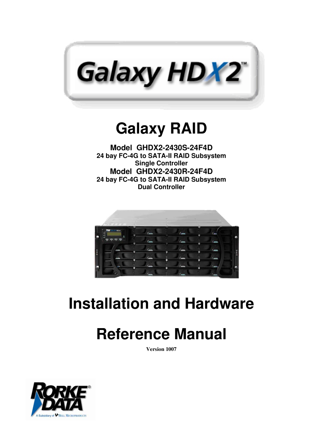
Model GHDX2-2430S-24F4D
24bay FC-4G to SATA-II RAID Subsystem Single Controller
Model GHDX2-2430R-24F4D
24bay FC-4G to SATA-II RAID Subsystem Dual Controller
Installation and Hardware
Reference Manual
Version 1007