Chapter 3 Subsystem Monitoring
|
|
| thresholds is violated. | |
|
|
|
| |
4 | BBU | Green | ON indicates BBU is present. | |
Link | ||||
|
|
| ||
|
|
|
| |
|
|
| FLASHING indicates there is active traffic through | |
5 | Hst Bsy | Green | the host ports. | |
|
|
| OFF indicates there is no activity on the host ports. | |
|
|
|
| |
|
|
| FLASHING indicates there is active traffic on the | |
6 | Drv Bsy | Green | drive channels. | |
OFF indicates there is no activity on the drive | ||||
|
|
| ||
|
|
| channels. | |
|
|
|
|
Table
3.2.1.1Fibre Port LEDs
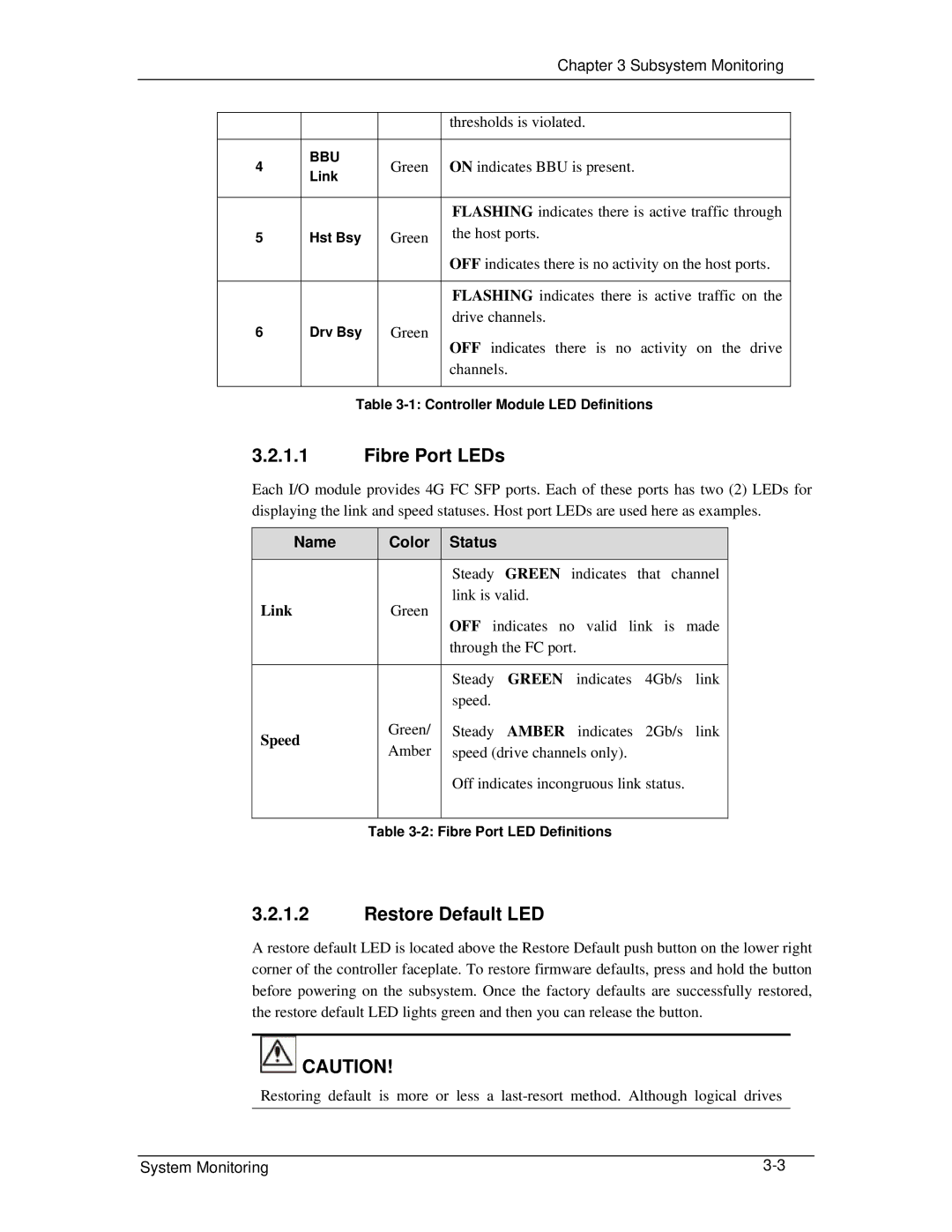
Each I/O module provides 4G FC SFP ports. Each of these ports has two (2) LEDs for displaying the link and speed statuses. Host port LEDs are used here as examples.
Name |
| Color | Status |
|
|
|
|
|
|
| Steady GREEN indicates that channel |
Link |
| Green | link is valid. |
| OFF indicates no valid link is made | ||
|
|
| |
|
|
| through the FC port. |
|
|
|
|
|
|
| Steady GREEN indicates 4Gb/s link |
|
|
| speed. |
Speed |
| Green/ | Steady AMBER indicates 2Gb/s link |
| Amber | speed (drive channels only). | |
|
| ||
|
|
| Off indicates incongruous link status. |
|
|
|
|
| Table | ||
3.2.1.2Restore Default LED
A restore default LED is located above the Restore Default push button on the lower right corner of the controller faceplate. To restore firmware defaults, press and hold the button before powering on the subsystem. Once the factory defaults are successfully restored, the restore default LED lights green and then you can release the button.
![]() CAUTION!
CAUTION!
Restoring default is more or less a
System Monitoring |
