Chapter 1: Introduction
Figure 1-12: Cooling Module
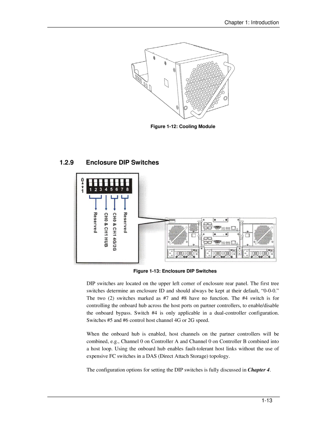
1.2.9Enclosure DIP Switches
Figure 1-13: Enclosure DIP Switches
DIP switches are located on the upper left corner of enclosure rear panel. The first tree switches determine an enclosure ID and should always be kept at their default,
When the onboard hub is enabled, host channels on the partner controllers will be combined, e.g., Channel 0 on Controller A and Channel 0 on Controller B combined into a host loop. Using the onboard hub enables
The configuration options for setting the DIP switches is fully discussed in Chapter 4.