Appendix B:
Pin Assignments
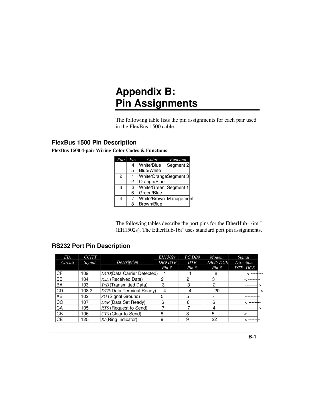
The following table lists the pin assignments for each pair used in the FlexBus 1500 cable.
FlexBus 1500 Pin Description
FlexBus 1500 4-pair Wiring Color Codes & Functions
Pair Pin
Color
Function
1
2
3
4
4 | White/Blue | Segment 2 |
5 | Blue/White |
|
1 | White/Orange | Segment 3 |
2 | Orange/Blue |
|
3 | White/Green | Segment 1 |
6 | Green/Blue |
|
7 | White/Brown | Management |
8 | Brown/Blue |
|
The following tables describe the port pins for the
RS232 Port Pin Description
EIA
Circuit
CF
BB
BA
CD
AB
CC
CA
CB
CE
CCITT
Signal
109
104
103
108.2
102
107
105
106
125
Description
DCD (Data Carrier Detected)
RxD (Received Data)
TxD (Transmitted Data)
DTR (Data Terminal Ready)
SG (Signal Ground)
DSR (Data Set Ready)
RTS
CTS
RI (Ring Indicator)
EH1502s
DB9 DTE
Pin #
1
2
3
4
5
6
7
8
9
PC DB9
DTE
Pin #
1
2
3
4
5
6
7
8
9
Modem
DB25 DCE
Pin #
8
3
2
20
7
6
4
5
22
Signal
Direction
DTE
<
<
<
<
<
