|
|
|
|
| Appendix A. Pinouts | ||||
|
|
|
|
|
|
|
| Table | |
|
|
|
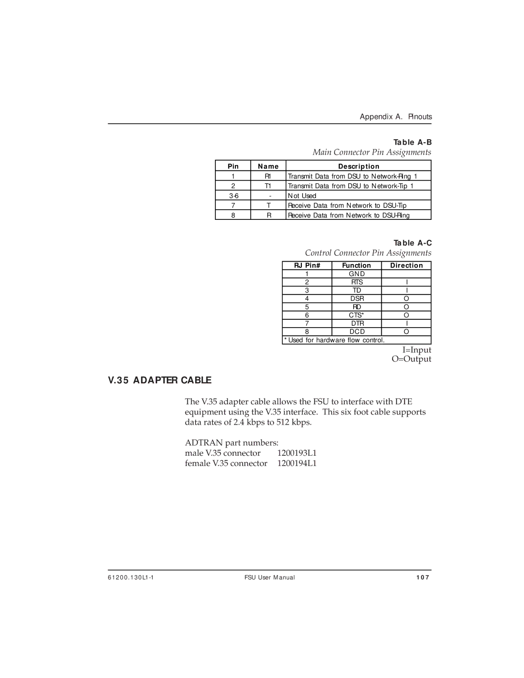
| Main Connector Pin Assignments | |||||
|
|
|
|
|
|
|
|
|
|
| Pin | Name |
|
| Description |
|
| ||
| 1 | R1 |
| Transmit Data from DSU to |
| ||||
| 2 | T1 |
| Transmit Data from DSU to |
| ||||
| - |
| Not Used |
|
|
|
|
| |
| 7 | T |
| Receive Data from Network to |
| ||||
| 8 | R |
| Receive Data from Network to |
| ||||
|
|
|
|
|
|
|
| Table | |
|
|
|
| Control Connector Pin Assignments | |||||
|
|
|
|
|
|
|
|
|
|
|
|
|
| RJ Pin# | Function |
| Direction |
| |
|
|
| 1 | GND |
|
|
| ||
|
|
| 2 | RTS |
| I |
| ||
|
|
| 3 | TD |
| I |
| ||
|
|
| 4 | DSR |
| O |
| ||
|
|
| 5 | RD |
| O |
| ||
|
|
| 6 | CTS* |
| O |
| ||
|
|
| 7 | DTR |
| I |
| ||
|
|
| 8 | DCD |
| O |
| ||
|
|
| *Used for hard | ware flow contro | l | . |
|
| |
|
|
|
|
|
|
|
| I=Input | |
|
|
|
|
|
|
|
| O=Output | |
V.35 ADAPTER CABLE
The V.35 adapter cable allows the FSU to interface with DTE equipment using the V.35 interface. This six foot cable supports data rates of 2.4 kbps to 512 kbps.
ADTRAN part numbers:
male V.35 connector | 1200193L1 |
female V.35 connector | 1200194L1 |
FSU User Manual | 107 |
