Chapter 7. Configuring the Network Port
When connecting to an external DSU, the FSU emulates an externally timed DTE interface connected directly to the DCE interface of the external device. Therefore, the connection between the FSU and the DSU is a direct connection.
|
| 1 | DTE PORT 1 |
|
|
|
| ||
|
| 2 DTE PORT 2 |
| |
| 1 CONFIG | 3 | NETWORK PORT |
|
|
| |||
|
| 4 IP ROUTING |
| |
|
| 5 SYSTEM CONFIG |
| |
|
|
|
|
|
1 INTERFACE TYPE |
| 1 RS232 |
|
|
| |
| 2 V.35 |
|
|
|
| |
|
| 3 NETWORK |
|
|
|
|
|
| 1 LOOP RATE (available when |
|
|
| |
|
|
|
|
| ||
|
| NETWORK interface type is |
|
|
| |
2 PHYSICAL LAYER OPTIONS |
| selected) |
| 1 56K | ||
|
|
|
|
| 2 64K | |
|
| 2 CLOCK SOURCE (available when |
|
|
| |
|
|
|
|
| ||
|
| NETWORK interface type is |
|
|
| |
|
| selected) |
| 1 MASTER | ||
|
|
|
|
| 2 FROM NETWORK |
|
|
| 1 NETWORK BIT RATE (available |
| 56K and 64K | ||
|
|
| ||||
|
| when RS232 or V.35 interface type |
| available for RS232 | ||
|
| is selected) |
| and V.35 interfaces. | ||
|
|
|
|
| Additional rates of |
|
|
|
|
|
| 112K through 512K | |
|
|
|
|
| available for V.35 | |
|
|
|
|
| interface. |
|
|
| 1 SIGNALING TYPE |
| 1 NONE | ||
|
|
| ||||
3 FRAME RELAY OPTIONS |
| 2 T391 |
| 2 LMI |
| |
|
| 3 ANSI |
| |||
|
| 3 N391 |
| 4 |
| |
|
| 4 N392 |
|
|
|
|
|
| 5 N393 |
|
| 1 DO NOT NOTIFY |
|
|
| 6 REMOTE FECN NOTIFICATION |
|
| ||
|
|
|
|
| 2 NOTIFY REMOTE ON FECN | |
4 LLC2 OPTIONS |
| 1 LLC2 ACK TIMEOUT |
|
|
| |
|
|
|
| |||
5 IP ADDRESS |
| 2 LLC2 N2 RETRY COUNTER |
|
|
| |
| 3 LLC2 k WINDOW SIZE |
|
|
|
| |
|
| 4 LLC2 POLL TIMEOUT |
|
|
|
|
6 SUBNET MASK |
| 5 LLC2 BUSY TIMEOUT |
|
|
|
|
| 6 LLC2 REJECT TIMEOUT |
|
|
|
| |
|
| 7 LLC2 |
|
|
|
|
7 TRANSMIT RIP REQUESTS |
| 1 NO |
|
|
| |
|
|
|
| |||
8 PROCESS RECEIVED RIP PACKETS |
| 2 YES |
|
|
| |
9 PRIORITY QUEUE RATIO (N:1) |
|
|
|
|
|
|
Figure
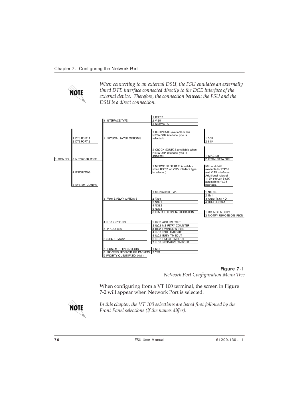
Network Port Configuration Menu Tree
When configuring from a VT 100 terminal, the screen in Figure
In this chapter, the VT 100 selections are listed first followed by the Front Panel selections (if the names differ).
70 | FSU User Manual |
