Chapter 2. Installation
Frame
Relay
|
|
|
|
|
|
|
|
| DSU III AR |
|
|
| A |
| B |
| C | ||||||
|
|
|
|
|
|
|
|
| ENTER |
| 1 |
| 2 |
| 3 |
| |||||||
|
|
|
|
|
|
|
|
|
|
|
|
|
|
|
|
|
| D |
| E |
| F | |
|
|
|
|
|
|
|
|
|
|
|
|
|
|
|
|
|
| 4 |
| 5 |
| 6 |
|
|
|
|
|
|
|
|
|
|
|
|
|
|
|
|
|
|
|
|
|
|
|
|
|
|
|
|
|
|
|
|
|
|
|
|
|
|
|
|
|
|
|
|
|
|
|
|
|
|
|
|
|
|
|
|
|
|
|
|
|
|
|
|
|
|
| 7 |
| 8 |
| 9 |
|
| RS CS TD RD CD ALM TST |
| SHIFT |
|
| QUICK | |||||||||||||||||
|
|
|
|
|
|
|
|
|
|
|
|
|
|
|
| CANCEL |
| * |
| 0 |
| # |
|
DSU/CSU
RS232 or V.35 Cable
Cable
VT 100 Terminal
TELCO | ON |
|
MAIN | BACKUP | DCE |
|
|
|
| OFF |
|
| DTE 1 | DTE 2 |
| CONTROL |
|
|
|
|
| 115VAC 60Hz |
RS232 or V.35 | RS232 or V.35 |
Cable | Cable |
DTE DeviceDTE Device
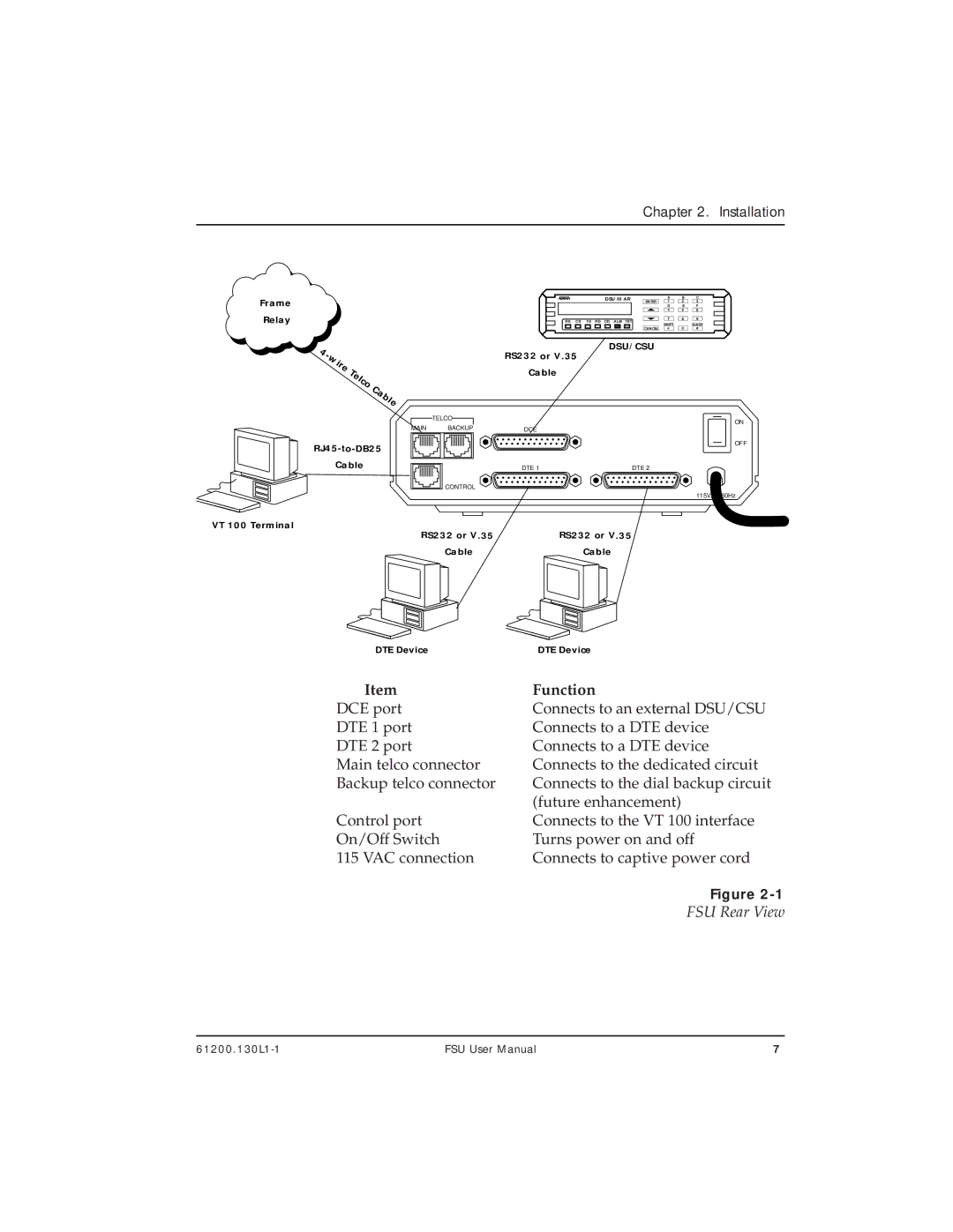
Item | Function |
DCE port | Connects to an external DSU/CSU |
DTE 1 port | Connects to a DTE device |
DTE 2 port | Connects to a DTE device |
Main telco connector | Connects to the dedicated circuit |
Backup telco connector | Connects to the dial backup circuit |
| (future enhancement) |
Control port | Connects to the VT 100 interface |
On/Off Switch | Turns power on and off |
115 VAC connection | Connects to captive power cord |
| Figure |
| FSU Rear View |
FSU User Manual | 7 |
