Contents
ISU
Trademark
021S5 RJ-49C
1202086L1
1202086L2
Canadian Emissions Requirements
Canadian Equipment Limitations
Quick Start Guide
SPID1/LDN1
Table of Contents
Table of Contents
Txinit Txfa TXADD01 Txdeq Tanull Tcid
107
List of Figures
Table of Contents
List of Tables
Viii
Isdn Overview
Product Overview
ISU 512 Rear Panel
Understanding Isdn and the ISU
ISU 512 Interoperability
Videoconferencing
Recommended Operating Protocols
ISU 512 Synchronous Rates
Understanding Isdn and the ISU
Following instructions only apply to North American switches
Chapter Ordering Isdn
Ordering Isdn
Network Connection
Chapter Installation
Installation
Smart Dial String Formats
DTE Data Connection
Dial Interface Connection
Installation
Maintenance Interface
Software Update
Set the COM port for 38400, 8, 1, n and no flow control
VT 100 Menu Interface
VT 100 Configuration Menu
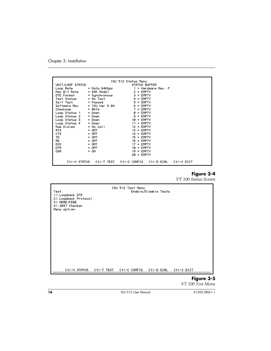
VT 100 Status Screen VT 100 Test Menu
VT 100 Dial Menu
Installation
Network Connection Status
Chapter Operation
Initial Self Test
Menu Structure
Main Menu
LCD Display of the Main Menu
Status Menu
Basic Menu Traversal
Front Panel
ISU 512 Front View
LCD Window
Numeric Keypad
Up and Down Arrows
LED Description
Operation
Chapter Configuration
Using Isdn Basic Rate Switched Service
Configuration Menu
Configuration
Call Type
Configuring Network Options for Dial Operation
Switch Type
Data 64 kbps default
Speech
Audio
Data 56 kbps
Outside of North America, SPIDs do not have to be entered
Setting the Spid
Terminal Identification
Setting the LDN
Dial Options
Dial Options Menu
Front Panel
RS-366
Sec or EON
Sec or EON default
Wait for EON
Security
25 bis
Disabled
Enabled
Auto Answer
Dump all calls
Select Ansr if SN0. . .9 under Call Screening
Connect Timeout
Call Screening
Remote Download RDL
Remote Access
Call Screening again
Remote Supervision
Maintenance Setup
Port Mode
Auto Traps
Adlp Address
Call NumID
Leased Line Menu
Configuring the ISU 512 for Leased Digital Service
Clock Mode
Leased Application with Channel Banks
Channel Rate
Limited Distance Modem Application
Test Remote
Setting DTE Options
Maximum Bit Rate
RS-366 Y Cable
Connector Type
RS-530 to V.35 Cable
DTR Options
CTS Options
CD Options
DSR Options
Bonding Setup
Txinit
Txfa
TXADD01
Txdeq
Tanull
Tcid
Call Stagger
Transparent 2 X Clear Channel Protocol
Quick Setup Configuration
Dial 512K
Dial 336K
Dial 384K
Dial 448K
Leased Master
Video 384K
Video 336K
Leased Slave and Ldm SlvMstr
Dialing Options
Store/Review Number
Configuring the ISU 512 for V.25 BIS IN-BAND Dialing
Chapter Testing
Test Options
Loopback DTE
Loopback Protocol
Checker
Near-End Block Errors/Far-End Block Errors NEBE/FEBE
Software Version
Testing
If AN Isdn Network Line Reads Down
Chapter Troubleshooting
If Self Test Fails
Troubleshooting
If the Display Reads TEI1
If the Display Reads TEI2
If the Display Reads SPID1,3,5, or
If the Display Reads SPID2,4,6, or
CONFIG, Netw. options, Dial Line, Terminal ID, and SPID/LDN
Chapter Specifications Summary
Specifications and Features
Channel Switch Compatibility
Power
Channel Aggregation
Display
NET REM Loopback
Appendix a Status Buffer Messages
Status Line Messages
Ringing
Accessinfodisc
Badinfoelem
Bearcapnotava
Bonding +
Callrejected
Capnotimplement
Chandoesnotexi
Channotimpleme
Dpump END Rcvd
Facilitynotimp
Facilityrejected
Facilitynotsub
Incomingcallba
Incompatibledest
Intrworking UNS
Invalidcallref
Mandatoryiemis
Network Busy
Networkcongesti
Networkoutofo
Protocolerror
Servicenotavail
Normalclearing
Numberchanged
Timerexpiry
Temporaryfailure
Unassignednumber
Unspecifiedcause
Wrongmsgforst
Set Primary
=Enable ISU 512 answers all calls default
Appendix B Register List
=Ignore DTR default
50=Wait for 5 seconds or EON default
=Disable default
Appenidix B. S-Register List
Appenidix B. S-Register List
Appendix C AT Commands
Commands should be entered without the AT prefix
AT Commands
Table C-A
Appendix C. AT Commands
5ESS
Appendix C. AT Commands
EIA-232 to DB-25 Adapter Connector
Appendix D Pinouts
RJ-45 Isdn Line Interface
Table D-A
Pinouts for IFC RJ-45 Connectors
EIA-232, RS-366, and RS-530 Connector
Connector
Table D-B
Table D-C
RS-366 Dialing Port Pinouts
M e
Table D-D
RS-530 Pinouts
Table D-E
Pinouts
Table D-F
RS-530-to-V.35 Adapter Cable Pinouts
Figure D-5
Figure D-6
Appendix D. Pinouts
Acronyms
Acronyms
Glossary
2B1Q
Ccitt
DDS
Isdn
NT1
Interface S reference point
Xmodem
106
Index
Numerics
Index
Isdn
110
TXADD01 47 Txdeq 47 Txfa 47 Txinit
112
Product Support Information
Presales Inquiries and Applications Support
Post-Sale Support
Repair and Return