Chapter 2. Installation
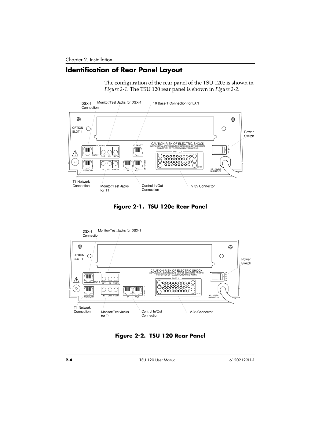
Identification of Rear Panel Layout
The configuration of the rear panel of the TSU 120e is shown in Figure
10 Base T Connection for LAN | |
Connection |
|
OPTION
SLOT 1
PORT 0.2
|
|
|
|
NETWORK | IN OUT | ||
|
| ||
Power
Switch
| 10 BASE T | SUPPLEMENTAL EARTH GROUND MUST BE CONNECTED PRIOR TO | P |
|
| CONNECTION OF TELECOMMUNICATIONS WIRING | O |
|
| PORT 0.1 | W |
|
| E | |
|
|
| R |
| C |
|
|
| H |
|
|
| A |
|
|
| I | V.35 |
|
IN | N |
| |
OUT |
| 50/60HZ.2A |
T1 Network |
|
|
|
Connection | Monitor/Test Jacks | Control In/Out | V.35 Connector |
| for T1 | Connection |
|
Figure 2-1. TSU 120e Rear Panel
| Monitor/Test Jacks for |
| |
Connection | |
OPTION
SLOT 1
PORT 0.2
|
|
|
|
NETWORK | IN OUT | ||
|
| ||
|
| SUPPLEMENTAL EARTH GROUND MUST BE CONNECTED PRIOR TO | P |
|
| CONNECTION OF TELECOMMUNICATIONS WIRING | O |
|
| PORT 0.1 | W |
|
| E | |
|
|
| R |
| C |
|
|
| H |
|
|
| A |
|
|
| I | V.35 |
|
IN | N |
| |
OUT |
| 50/60HZ.2A | |
|
|
|
Power Switch
T1 Network |
|
|
|
Connection | Monitor/Test Jacks | Control In/Out | V.35 Connector |
| for T1 | Connection |
|
Figure 2-2. TSU 120 Rear Panel
TSU 120 User Manual |
