|
| Chapter 5. Configuration Menu |
|
|
|
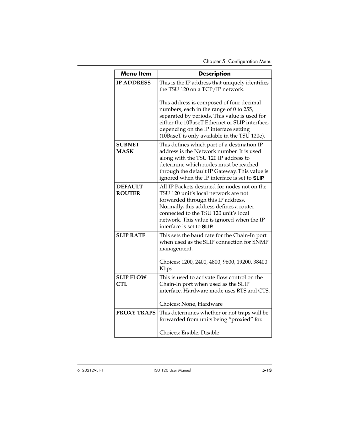
| Menu Item | Description |
|
|
|
| IP ADDRESS | This is the IP address that uniquely identifies |
|
| the TSU 120 on a TCP/IP network. |
|
| This address is composed of four decimal |
|
| numbers, each in the range of 0 to 255, |
|
| separated by periods. This value is used for |
|
| either the 10BaseT Ethernet or SLIP interface, |
|
| depending on the IP interface setting |
|
| (10BaseT is only available in the TSU 120e). |
|
|
|
| SUBNET | This defines which part of a destination IP |
| MASK | address is the Network number. It is used |
|
| along with the TSU 120 IP address to |
|
| determine which nodes must be reached |
|
| through the default IP Gateway. This value is |
|
| ignored when the IP interface is set to SLIP. |
|
|
|
| DEFAULT | All IP Packets destined for nodes not on the |
| ROUTER | TSU 120 unit’s local network are not |
|
| forwarded through this IP address. |
|
| Normally, this address defines a router |
|
| connected to the TSU 120 unit’s local |
|
| network. This value is ignored when the IP |
|
| interface is set to SLIP. |
|
|
|
| SLIP RATE | This sets the baud rate for the |
|
| when used as the SLIP connection for SNMP |
|
| management. |
|
| Choices: 1200, 2400, 4800, 9600, 19200, 38400 |
|
| Kbps |
|
|
|
| SLIP FLOW | This is used to activate flow control on the |
| CTL | |
|
| interface. Hardware mode uses RTS and CTS. |
|
| Choices: None, Hardware |
|
|
|
| PROXY TRAPS | This determines whether or not traps will be |
|
| forwarded from units being “proxied” for. |
|
| Choices: Enable, Disable |
|
|
|
TSU 120 User Manual |