List of Tables
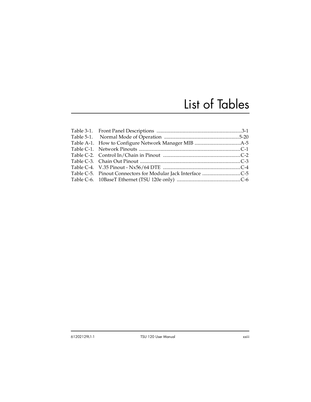
Table | Front Panel Descriptions | |
Table | Normal Mode of Operation | |
Table | How to Configure Network Manager MIB | |
Table | Network Pinouts | |
Table | Control In/Chain in Pinout | |
Table | Chain Out Pinout | |
Table | V.35 Pinout - Nx56/64 DTE | |
Table | Pinout Connectors for Modular Jack Interface | |
Table | 10BaseT Ethernet (TSU 120e only) |
TSU 120 User Manual | xxiii |
