Digital I/O Operation
The digital port can be configured (see Figure
OUT 0 (pin 1) | This port can only be used as an | ||
OUT 1 (pin 2) | This port can only be used as an | ||
IN/OUT 2 (pin 3) | This port can be programmed to be either a high impedance input or an | ||
Common (pin 4) | This pin is the common connection for the Digital I/O ports. | ||
|
|
|
|
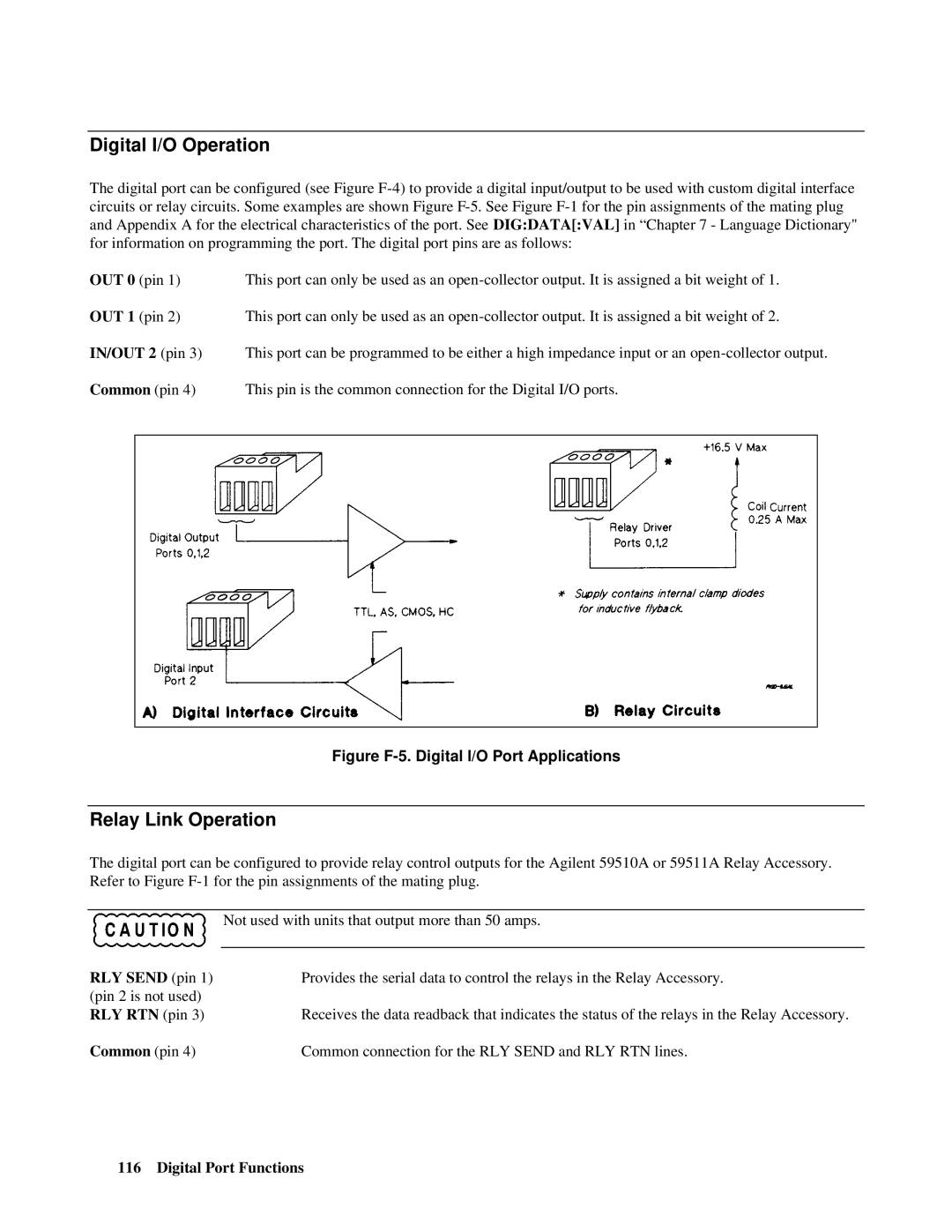
Figure F-5. Digital l/O Port Applications
Relay Link Operation
The digital port can be configured to provide relay control outputs for the Agilent 59510A or 59511A Relay Accessory. Refer to Figure
Not used with units that output more than 50 amps.
RLY SEND (pin 1) (pin 2 is not used) RLY RTN (pin 3)
Provides the serial data to control the relays in the Relay Accessory.
Receives the data readback that indicates the status of the relays in the Relay Accessory.
Common (pin 4) | Common connection for the RLY SEND and RLY RTN lines. |