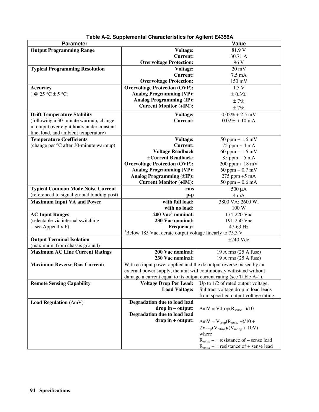
Table
Parameter
Output Programming Range
Typical Programming Resolution
Accuracy
( @ 25 °C ± 5 °C)
Drift Temperature Stability (following a
Voltage:
Current:
Overvoltage Protection:
Voltage:
Current:
Overvoltage Protection:
Overvoltage Protection (OVP):
Analog Programming (VP):
Analog Programming (IP):
Current Monitor (+IM):
Voltage:
Current:
Value
81.9 V
30.71A
96 V
20mV
7.5 mA
150 mV
1.5 V
±0.3%
± 7%
± 7%
0.02% + 2.5 mV
0.02% + 10 mA
Temperature Coefficients
(change per °C after
Typical Common Mode Noise Current
(referenced to signal ground binding post)
Maximum Input VA and Power
AC Input Ranges
(selectable via internal switching - see Appendix F)
Output Terminal Isolation
(maximum, from chassis ground)
Maximum AC Line Current Ratings
Maximum Reverse Bias Current:
Remote Sensing Capability
Load Regulation (ΔmV)
Voltage: | 50 ppm + 1.6 mV |
Current: | 75 ppm + 4 mA |
Voltage Readback | 60 ppm + 1.6 mV |
±Current Readback: | 85 ppm + 5 mA |
Overvoltage Protection (OVP): | 200 ppm + 18 mV |
Analog Programming (VP): | 60 ppm + 0.7 mV |
Analog Programming (±IP): | 275 ppm +5 mA |
Current Monitor (+IM): | 50 ppm + 0.6 mA |
rms | 500 μA |
4 mA | |
with full load: | 3800 VA; 2600 W, |
with no load: | 100 W |
200 Vac1 nominal: | |
230 Vac nominal: | |
Frequency: | |
1Below 185 Vac, derate output voltage linearly to 75.3 V | |
| ±240 Vdc |
|
|
200 Vac nominal: | 19 A rms (25 A fuse) |
230 Vac nominal: | 19 A rms (25 A fuse) |
With ac input power applied and the dc output reverse biased by an external power supply, the unit will continuously withstand without damage a current equal to its output current rating (see Table
Up to 1/2 of rated output voltage. Subtract voltage drop in load leads from specified output voltage rating.
ΔmV = Vdrop(Rsense– )/10
ΔmV = Vdrop(Rsense +)/10 +
2Vdrop(Vrating)/(Vrating + 10V)
where
Rsense – = resistance of – sense lead Rsense + = resistance of + sense lead
94 Specifications