*SRE
Meaning and Type
Service Request Enable Device Interface
Description
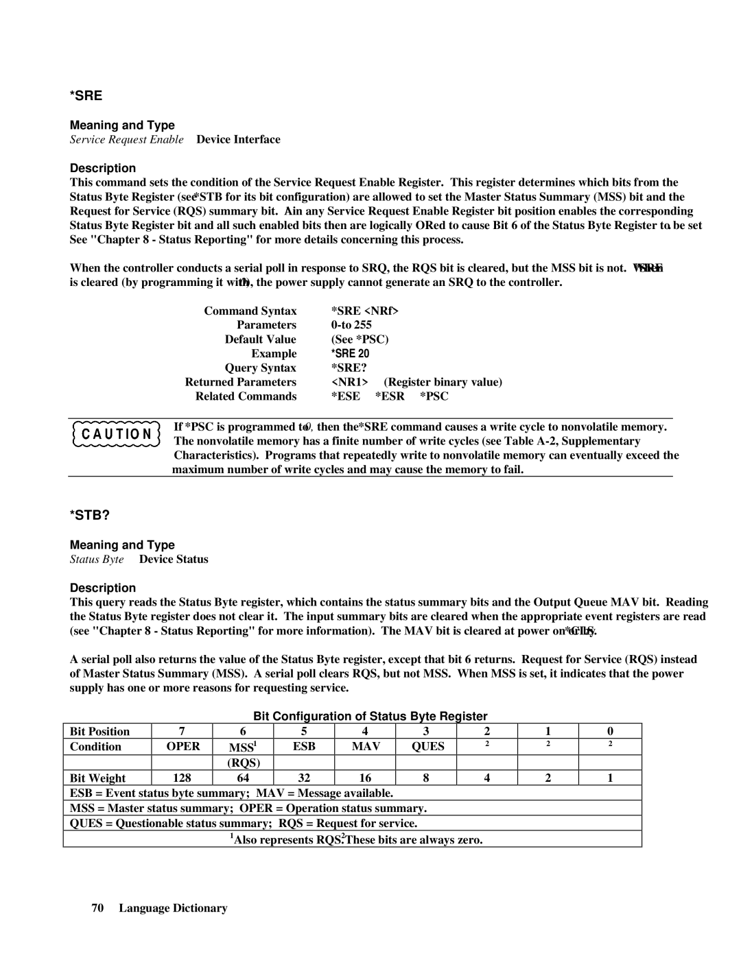
This command sets the condition of the Service Request Enable Register. This register determines which bits from the Status Byte Register (see *STB for its bit configuration) are allowed to set the Master Status Summary (MSS) bit and the Request for Service (RQS) summary bit. A 1 in any Service Request Enable Register bit position enables the corresponding Status Byte Register bit and all such enabled bits then are logically ORed to cause Bit 6 of the Status Byte Register to be set. See "Chapter 8 - Status Reporting" for more details concerning this process.
When the controller conducts a serial poll in response to SRQ, the RQS bit is cleared, but the MSS bit is not. When *SRE is cleared (by programming it with 0), the power supply cannot generate an SRQ to the controller.
Command Syntax | *SRE <NRf> | |
Parameters |
| |
Default Value | (See *PSC) | |
Example | *SRE 20 |
|
Query Syntax | *SRE? |
|
Returned Parameters | <NR1> | (Register binary value) |
Related Commands | *ESE | *ESR *PSC |
If *PSC is programmed to 0, then the *SRE command causes a write cycle to nonvolatile memory. The nonvolatile memory has a finite number of write cycles (see Table
*STB?
Meaning and Type
Status Byte Device Status
Description
This query reads the Status Byte register, which contains the status summary bits and the Output Queue MAV bit. Reading the Status Byte register does not clear it. The input summary bits are cleared when the appropriate event registers are read (see "Chapter 8 - Status Reporting" for more information). The MAV bit is cleared at power on or by *CLS.
A serial poll also returns the value of the Status Byte register, except that bit 6 returns. Request for Service (RQS) instead of Master Status Summary (MSS). A serial poll clears RQS, but not MSS. When MSS is set, it indicates that the power supply has one or more reasons for requesting service.
Bit Position
Condition
Bit Weight
7
OPER
128
Bit Configuration of Status Byte Register
6 | 5 | 4 | 3 | 2 |
MSS1 | ESB | MAV | QUES | 2 |
(RQS) |
|
|
|
|
64 | 32 | 16 | 8 | 4 |
1
2
2
0
2
1
ESB = Event status byte summary; MAV = Message available.
MSS = Master status summary; OPER = Operation status summary.
QUES = Questionable status summary; RQS = Request for service.
1Also represents RQS. 2These bits are always zero.
70 Language Dictionary
