PDU Display Interface
PDU Alarms
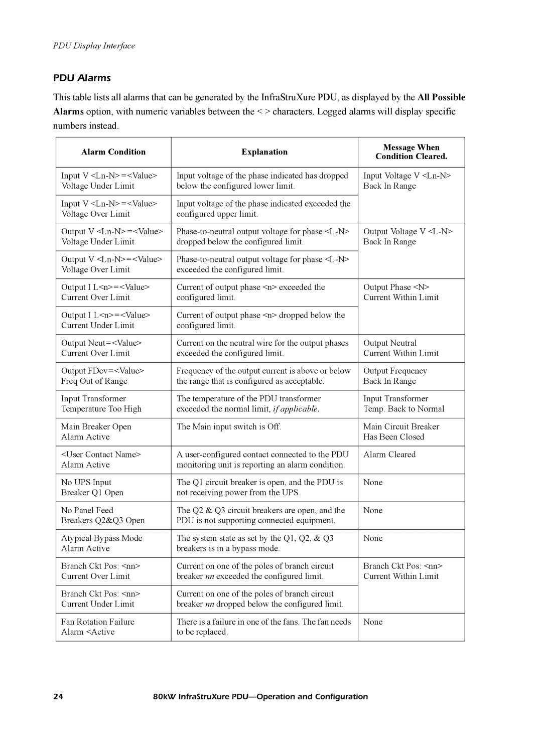
This table lists all alarms that can be generated by the InfraStruXure PDU, as displayed by the All Possible Alarms option, with numeric variables between the < > characters. Logged alarms will display specific numbers instead.
Alarm Condition | Explanation | Message When | |
Condition Cleared. | |||
|
| ||
|
|
| |
Input V | Input voltage of the phase indicated has dropped | Input Voltage V | |
Voltage Under Limit | below the configured lower limit. | Back In Range | |
|
|
| |
Input V | Input voltage of the phase indicated exceeded the |
| |
Voltage Over Limit | configured upper limit. |
| |
|
|
| |
Output V | Output Voltage V | ||
Voltage Under Limit | dropped below the configured limit. | Back In Range | |
|
|
| |
Output V |
| ||
Voltage Over Limit | exceeded the configured limit. |
| |
|
|
| |
Output I L<n>=<Value> | Current of output phase <n> exceeded the | Output Phase <N> | |
Current Over Limit | configured limit. | Current Within Limit | |
|
|
| |
Output I L<n>=<Value> | Current of output phase <n> dropped below the |
| |
Current Under Limit | configured limit. |
| |
|
|
| |
Output Neut=<Value> | Current on the neutral wire for the output phases | Output Neutral | |
Current Over Limit | exceeded the configured limit. | Current Within Limit | |
|
|
| |
Output FDev=<Value> | Frequency of the output current is above or below | Output Frequency | |
Freq Out of Range | the range that is configured as acceptable. | Back In Range | |
|
|
| |
Input Transformer | The temperature of the PDU transformer | Input Transformer | |
Temperature Too High | exceeded the normal limit, if applicable. | Temp. Back to Normal | |
|
|
| |
Main Breaker Open | The Main input switch is Off. | Main Circuit Breaker | |
Alarm Active |
| Has Been Closed | |
|
|
| |
<User Contact Name> | A | Alarm Cleared | |
Alarm Active | monitoring unit is reporting an alarm condition. |
| |
|
|
| |
No UPS Input | The Q1 circuit breaker is open, and the PDU is | None | |
Breaker Q1 Open | not receiving power from the UPS. |
| |
|
|
| |
No Panel Feed | The Q2 & Q3 circuit breakers are open, and the | None | |
Breakers Q2&Q3 Open | PDU is not supporting connected equipment. |
| |
|
|
| |
Atypical Bypass Mode | The system state as set by the Q1, Q2, & Q3 | None | |
Alarm Active | breakers is in a bypass mode. |
| |
|
|
| |
Branch Ckt Pos: <nn> | Current on one of the poles of branch circuit | Branch Ckt Pos: <nn> | |
Current Over Limit | breaker nn exceeded the configured limit. | Current Within Limit | |
|
|
| |
Branch Ckt Pos: <nn> | Current on one of the poles of branch circuit |
| |
Current Under Limit | breaker nn dropped below the configured limit. |
| |
|
|
| |
Fan Rotation Failure | There is a failure in one of the fans. The fan needs | None | |
Alarm <Active | to be replaced. |
| |
|
|
|
24 | 80kW InfraStruXure |
