Wiring and Connections
Ethernet 10/100 Base-T RJ-45 Wiring Configuration
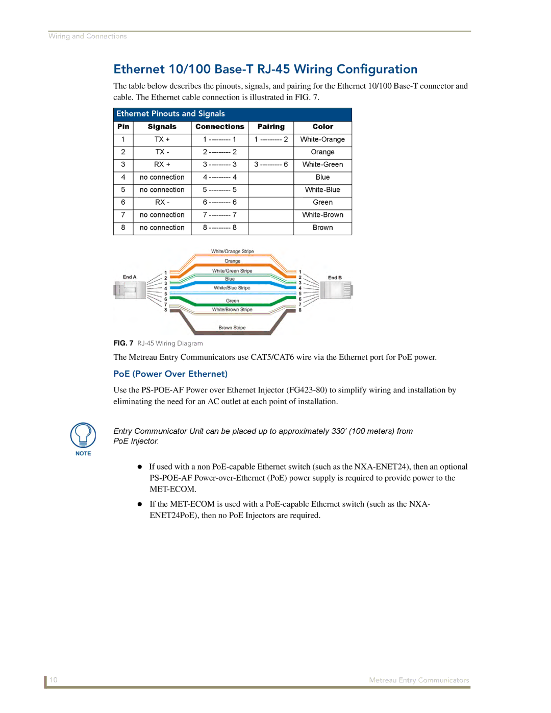
The table below describes the pinouts, signals, and pairing for the Ethernet 10/100
Ethernet Pinouts and Signals
Pin | Signals | Connections | Pairing | Color | ||
|
|
|
|
|
|
|
1 | TX + | 1 | 1 | 1 | 2 | |
|
|
|
|
|
|
|
2 | TX - | 2 | 2 |
|
| Orange |
|
|
|
|
|
|
|
3 | RX + | 3 | 3 | 3 | 6 | |
|
|
|
|
|
|
|
4 | no connection | 4 | 4 |
|
| Blue |
|
|
|
|
|
|
|
5 | no connection | 5 | 5 |
|
| |
|
|
|
|
|
|
|
6 | RX - | 6 | 6 |
|
| Green |
|
|
|
|
|
|
|
7 | no connection | 7 | 7 |
|
| |
|
|
|
|
|
|
|
8 | no connection | 8 | 8 |
|
| Brown |
|
|
|
|
|
|
|
FIG. 7 RJ-45 Wiring Diagram
The Metreau Entry Communicators use CAT5/CAT6 wire via the Ethernet port for PoE power.
PoE (Power Over Ethernet)
Use the
Entry Communicator Unit can be placed up to approximately 330’ (100 meters) from
PoE Injector.
If used with a non
If the
ENET24PoE), then no PoE Injectors are required.
10 | Metreau Entry Communicators |