Wiring and Connections
Wiring and Connections
Overview
To avoid any damage to the electronic component, installation must be performed in an ESD safe environment.
The installation section addresses the mounting and wiring of the Metreau Entry Communicators. After you have completed the installation you must consult the Using the Configuration Manager section of the Metreau Entry Communicators Operation/Reference Guide (available online at www.amx.com).
Additionally, consider the location of your installation. When possible, avoid facing the device in what would be considered high traffic areas.
Do not connect power to the Metreau Entry Communicators until the wiring is complete.
Rear Panel Connectors
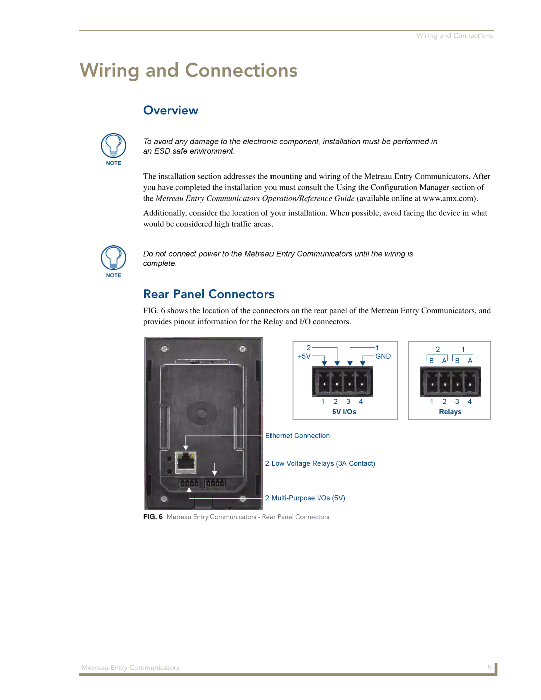
FIG. 6 shows the location of the connectors on the rear panel of the Metreau Entry Communicators, and provides pinout information for the Relay and I/O connectors.
2 |
|
|
|
| 1 | ||
|
|
| |||||
+5V |
|
|
|
|
|
| GND |
|
| ||||||
1 2 3 4
5V I/Os
Ethernet Connection
2 Low Voltage Relays (3A Contact)
2 1
BA![]()
![]() B A
B A
12 3 4
Relays
2
FIG. 6 Metreau Entry Communicators - Rear Panel Connectors
Metreau Entry Communicators | 9 |
|
|
