Manuals
/
AMX
/
Household Appliance
/
Home Security System
AMX
MET-ECOM-D
manual
Side Views, Top View
Models:
MET-ECOM-D
1
23
88
88
Download
88 pages
17.43 Kb
20
21
22
23
24
25
26
27
Specifications
Install
System Diagram
Ethernet Pinouts and Signals
Default
Wiring and Connections
Dimension
Using Zero Configuration
Intercom Setup
Command Buttons
Page 23
Image 23
Mounting and Installation
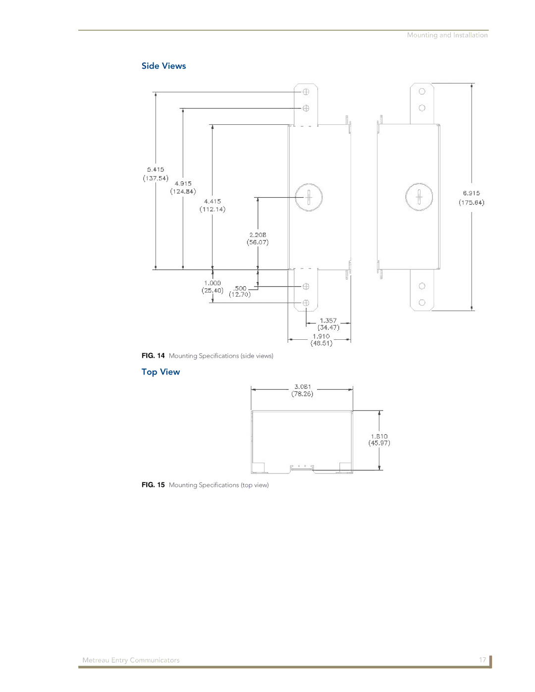
Side Views
FIG. 14
Mounting Specifications (side views)
Top View
FIG. 15
Mounting Specifications (top view)
Metreau Entry Communicators
17
Page 22
Page 24
Page 23
Image 23
Page 22
Page 24
Contents
Metreau Entry Communicators
AMX Limited Warranty and Disclaimer
Table of Contents
Using Zero Configuration
Programming
Creating Popup Pages
Overview
Metreau Entry Communicators
Metreau Entry Communicators Front Components
Front Components
Rear Components
Product Specifications MET-ECOM
MET-ECOM Specifications
Dimensions
MET-ECOM-D Specifications
Product Specifications MET-ECOM-D
MET-ECOM-D Specifications
Positioning the Camera
Camera Viewing Angle Adjustment
Default
Rear Panel Connectors
Wiring and Connections
Connections Pairing
Ethernet 10/100 Base-T RJ-45 Wiring Configuration
PoE Power Over Ethernet
Ethernet Pinouts and Signals
Port Wiring Specifications
Input/Output I/O Port Connections and Wiring
Relay Port Connections and Wiring
Connecting The Device via I/O
Installing the CAT5 Suppression Ferrite
Ferrite Installation Required
System Diagram Intercom
System Diagram
Wiring and Connections Metreau Entry Communicators
Dimensions
Mounting and Installation
MET-ECOM / MET-ECOM-D Installation Overview
Front View
Mounting Specifications
Top View
Side Views
Typical Installation Without Expansion Clips
Typical Installation Without Expansion Clips
Device and wall box must have an Earth ground
Installing the Wall Box Without the Use of Tabs
Recommended Cutout For Wall Box
Wall Surface Installation Using Expansion Clips
Replacement drywall clip sets must be ordered from AMX
Flat Surface Installation Points
Installing Into a Flat Surface Using Mounting Screws
Removing the Device From the Wall
Included in the Kit
Using the Optional Surface Mount Box
Provides mounting specifications for the CB-MET-ECOMS
Surface Mount Box Specifications
Installing the Metreau Entry Communicator
Ferrite Installation Required
Mounting and Installation
Connecting In a Network With a Dhcp Server
Using Zero Configuration
Bonjour Zero-Configuration Client
This case the serial number is 218001WHP2980023
Connecting In a Network Without a Dhcp Server
Internet Properties TCP/IP Properties dialog
Using Zero Configuration Metreau Entry Communicators
Configuration Manager Summary of Settings Page initial view
Using the Configuration Manager
Accessing the Configuration Manager
Command Buttons
Device Information
Summary of Device Settings
Summary of Device Settings
Checking the Firmware Version
Rebooting the Device
IP Settings
NetLinx Settings
Configuration Page Network IP Settings Tab
Configuration
Configuration Page Network IP Settings Tab
Setting the IP Address
Setting the DNS Address
Configuration Page NetLinx Settings Tab
Configuration Page NetLinx Settings Tab
Setting the Icsp Connection to the NetLinx Master
Configuration Page User Settings Tab
Configuration Page User Settings Tab
Setting a New Username and Password
Utility Meta Information
Device Utilities
Device Utilities
Images
Creating Display Images
Image File Requirements
File Upload
Save the file as a .BMP image FIG
TPDesign4 Resource Manager
Creating Dynamic Images
Create Dynamic Image dialog
Creating a New Dynamic Image
Deleting a Display Image From the Device
Uploading a Display Image To The Device
Audio/Video
Audio/Video Page Audio Settings Tab
Setting Device Audio
Audio/Video Page Audio Settings Tab
Video Codec
Audio/Video Page Video Settings Tab
Audio/Video Page Video Settings Tab
Camera/Video Stream Configuration
Audio/Video Page Display Settings Tab
Setting Device Video
Audio/Video Page Display Settings Tab
Setting the Display Settings On The Device
Programming
SENDCOMMANDs
Touch Panel Intercom Commands
Touch Panel Intercom Commands
MOD?
STREAM-GET
STREAM-PLAY
STREAM-STOP
RTP, Rtcp Video and Audio Streaming Commands
RTP, Rtcp Video and Audio Streaming Commands
GET Gain
GET Volume
SET Volume
SET Audio
Face Plate LED Commands
Face Plate LED Commands
Camera Commands
Camera Commands
GET CAM-SAT
SET CAM-CST
GET CAM-CST
SET CAM-SAT
SET DISP-BANNER
LCD Commands
LCD Commands
GET CAM-FLICK
GET DISP-CST
SET DISP-BRT
GET DISP-BRT
SET DISP-CST
System Commands
Commands
System Commands
Commands
GET DOOR-DESC
SET DOOR-DESC
Preparing the Master for communication via an IP
Before beginning the Upgrade process
Upgrading Firmware
Upgrading Firmware via an IP Address
Verifying and Upgrading the device firmware via an IP
Assigning Communication Settings and TCP/IP Settings
Select the device’s firmware file from the Files section FIG
Incorporating an Intercom Panel Into Your NetLinx System
Using the NetLinx Module
Panel Intercom Configuration
Intercom Setup
Setting Intercom Auto Answer
Setting the Intercom Session Timeout
Disabling All Doorbells
Door Setup
Assigning a Chime To a Doorbell
Door Chime Setup
Allowing a Panel To Be Monitored
Advanced Setup
Answering an incoming Intercom call
Allowing a Panel To Monitor
Naming a panel
Answering an Incoming Doorbell Call
Someone At The Door
Name Description Channel Address PortCode
Advanced Setup
Creating Intercom Pages
Ending a Doorbell Call
Door Setup
Door Chime Setup
Name Description Channel Address Level PortCode
Intercom Demo
Sample Intercom
Panel Directory Room Name Name of a panel
Setup
Setup
Someone At The Door
Someone At The Door
Door Answer Call popup
Doorbell Adjustments popup
Doorbell Adjustments Popup
Creating Popup Pages
Intercom Answer Call Popup
Intercom Answer Call popup
More Time Popup
More Time popup
Programming Metreau Entry Communicators
It’s Your World Take Control
Top
Page
Image
Contents