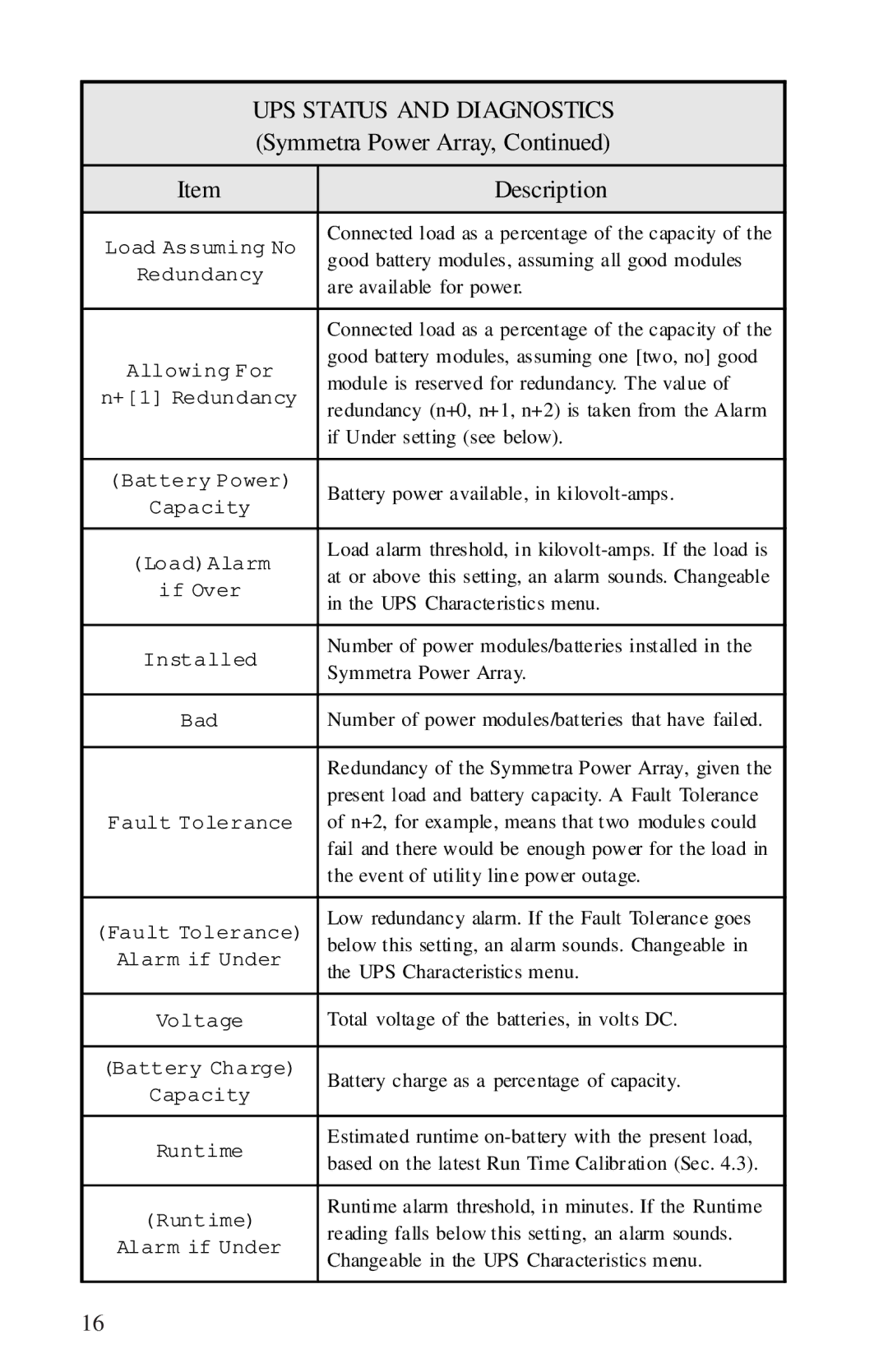
UPS STATUS AND DIAGNOSTICS | ||
(Symmetra Power Array, Continued) | ||
|
| |
Item | Description | |
|
| |
Load Assuming No | Connected load as a percentage of the capacity of the | |
good battery modules, assuming all good modules | ||
Redundancy | ||
are available for power. | ||
| ||
|
| |
| Connected load as a percentage of the capacity of the | |
Allowing For | good battery modules, assuming one [two, no] good | |
module is reserved for redundancy. The value of | ||
n+[1] Redundancy | ||
redundancy (n+0, n+1, n+2) is taken from the Alarm | ||
| ||
| if Under setting (see below). | |
|
| |
(Battery Power) | Battery power available, in | |
Capacity | ||
| ||
|
| |
(Load)Alarm | Load alarm threshold, in | |
at or above this setting, an alarm sounds. Changeable | ||
if Over | ||
in the UPS Characteristics menu. | ||
| ||
|
| |
Installed | Number of power modules/batteries installed in the | |
Symmetra Power Array. | ||
| ||
|
| |
Bad | Number of power modules/batteries that have failed. | |
|
| |
| Redundancy of the Symmetra Power Array, given the | |
| present load and battery capacity. A Fault Tolerance | |
Fault Tolerance | of n+2, for example, means that two modules could | |
| fail and there would be enough power for the load in | |
| the event of utility lin e power outage. | |
|
| |
(Fault Tolerance) | Low redundancy alarm. If the Fault Tolerance goes | |
below this setting, an alarm sounds. Changeable in | ||
Alarm if Under | the UPS Characteristics menu. | |
| ||
|
| |
Voltage | Total voltage of the batteries, in volts DC. | |
|
| |
(Battery Charge) | Battery charge as a percentage of capacity. | |
Capacity | ||
| ||
|
| |
Runtime | Estimated runtime | |
based on the latest Run Time Calibr ation (Sec. 4.3). | ||
| ||
|
| |
(Runtime) | Runtime alarm threshold, in minutes. If the Runtime | |
reading falls below this setting, an alarm sounds. | ||
Alarm if Under | ||
Changeable in the UPS Characteristics menu. | ||
| ||
|
| |
16
