Cyclades-PR2000
Network Protocol Menu (Continued)
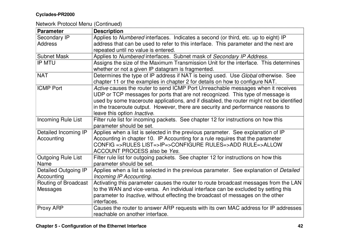
Parameter | Description |
Secondary IP | Applies to Numbered interfaces. Indicates a second (or third, etc. up to eight) IP |
Address | address that can be used to refer to this interface. This parameter and the next are |
| repeated until no value is entered. |
Subnet Mask | Applies to Numbered interfaces. Subnet mask of Secondary IP Address. |
IP MTU | Assigns the size of the Maximum Transmission Unit for the interface. This determines |
| whether or not a given IP datagram is fragmented. |
NAT | Determines the type of IP address if NAT is being used. Use Global otherwise. See |
| chapter 11 or the examples in chapter 2 for details on how to configure NAT. |
ICMP Port | Active causes the router to send ICMP Port Unreachable messages when it receives |
| UDP or TCP messages for ports that are not recognized. This type of message is |
| used by some traceroute applications, and if disabled, the router might not be identified |
| in the traceroute output. However, there are security and performance reasons to |
| leave this option Inactive. |
Incoming Rule List | Filter rule list for incoming packets. See chapter 12 for instructions on how this |
| parameter should be set. |
Detailed Incoming IP | Applies when a list is selected in the previous parameter. See explanation of IP |
Accounting | Accounting in chapter 10. IP Accounting for a rule requires that the parameter |
| CONFIG =>RULES LIST=>IP=>CONFIGURE RULES=>ADD RULE=>ALLOW |
| ACCOUNT PROCESS also be Yes. |
Outgoing Rule List | Filter rule list for outgoing packets. See chapter 12 for instructions on how this |
Name | parameter should be set. |
Detailed Outgoing IP | Applies when a list is selected in the previous parameter. See explanation of Detailed |
Accounting | Incoming IP Accounting. |
Routing of Broadcast | Activating this parameter causes the router to route broadcast messages from the LAN |
Messages | to the WAN and |
| parameter to Inactive, without effecting the broadcast of messages on the other |
| interfaces. |
Proxy ARP | Causes the router to answer ARP requests with its own MAC address for IP addresses |
| reachable on another interface. |
Chapter 5 - Configuration of the Ethernet Interface | 42 |