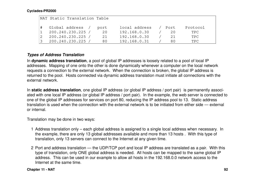
Installation Manual
Access Router
Cyclades-PR2000
Cyclades Corporation
Canadian DOC Notice
Cyclades-PR2000 Installation Manual
FCC Warning Statement
IP Bridge
Table of Contents
Special Keys
OSPF Configuration on the Interface
OSPF Global Configurations
The IP Protocol
Static Routing
Creation of user accounts and passwords
DB-25 Loopback Connector
Table of Contents
The WAN Interfaces
The LAN Interface
CHAPTER 1 HOW TO USE THIS MANUAL
Installation Assumptions
Text Conventions
Convention
Description
Icons
Icon
Cyclades Technical Support and Contact Information
Cyclades Corporation
Chapter 1 - How to Use This Manual
Phone + 01 510 Fax + 01 510 41829 Albrae Street Fremont, CA USA
Cyclades-PR2000
Back Panel of PR2000
CHAPTER 2 WHAT IS IN THE BOX
DB-25
Quick Installation Manual
Back Panel of PR2000
Chapter 3 Using CyROS Menus
Connection Using the Console Cable and a Computer or Terminal
PR2000 login super PR2000 Password
Config
All menus have the following elements
Special Keys
The CyROS Management Utility
Cyros Management Utility
Chapter 3 - Using CyROS Menus
Cyclades-PR2000
Example 1 Connection to an Internet Access Provider via Modem
CHAPTER 4 STEP-BY-STEP INSTRUCTIONS FOR COMMON APPLICATIONS
Speed 38.4k
Network Mask
Parameter
Example
Your Application
FIGURE 4.2 ETHERNET NETWORK PROTOCOL MENU PARAMETERS
STEP TWO
Parameter
Example
Your Application
Parameter
Example
Your Application
FIGURE 4.4 SWAN NETWORK PROTOCOL IP MENU PARAMETERS
Parameter
Example
Your Application
FIGURE 4.5 PPP ENCAPSULATION MENU PARAMETERS
Parameter
Example
Your Application
Parameter
STEP SEVEN
Parameter
Example
Your Application
Instructions for creating a backup of the configuration file
Instructions for listing the configuration
Example 2 A LAN-to-LAN Example Using Frame Relay
Central Offices
Remote Site’s
100.130.130.1
Parameter
Example
Your Application
FIGURE 4.10 ETHERNET NETWORK PROTOCOL MENU PARAMETERS
Parameter
Example
Your Application
DSU/CSU, the Clock Source is External
Parameter
Example
Your Application
FIGURE 4.12 SWAN NETWORK PROTOCOL IP MENU PARAMETERS
sending end must be using the same header
Parameter
Example
Your Application
FIGURE 4.14 DLC CONFIGURATION MENU PARAMETERS
Parameter
Example
Your Application
Parameter
Example
Your Application
FIGURE 4.15 STATIC ROUTE MENU PARAMETERS
Instructions for creating a backup of the configuration file
Instructions for listing the configuration
Cyclades-PR2000
Chapter 4 - Step-by-Step Instructions
Example 3 Link Backup
FIGURE 4.16 PRIMARY AND SECONDARY BACKUP LINKS BETWEEN TWO LANS
Parameter
Example
Your Application
Parameter
Parameter
Example
Your Application
Parameter
This parameter has no effect for link backup. For load
Parameter
Example
FIGURE 4.21 STATIC BACKUP ROUTE PARAMETERS
Parameter
Example
Your Application
Instructions for creating a backup of the configuration file
Instructions for listing the configuration
CHAPTER 5 CONFIGURATION OF THE ETHERNET INTERFACE
The IP Network Protocol
Parameter
Description
Incoming IP Accounting
Parameter
Description
IP Bridge
FIGURE 5.1 IP BRIDGE EXAMPLE
Description
Other Parameters
Parameter
CHAPTER 6 THE SWAN AND ASYNC INTERFACES
Parameter
Description
the Clock Source is always External
STEP TWO
Parameter
Description
Config
CHAPTER 7 NETWORK PROTOCOLS
Description
The IP Protocol
Parameter
Detailed Incoming IP Accounting
Parameter
Description
The Transparent Bridge Protocol
Parameter
Description
For the Spanning Tree Algorithm, a priority is given to each link in the router and to
CHAPTER 8 DATA-LINK PROTOCOLS ENCAPSULATION
PPP The Point-to-Point Protocol
Applies when Enable Van Jacobson IP Header Compression is Yes . This
Parameter
LCP Link Control Protocol messages are normally exchanged to monitor the status of
Parameter
Description
CHAR
communication. When Start is used, a connection is attempted as soon as the line
Parameter
Description
PPPCHAR
HDLC
Frame Relay
Traffic Control based on Data Link Connection
Description
end must be using the same header type NLPID or SNAP as the router on the receiving end
Parameter
DLCI
200.1.1.1
Router
200.1.1.1
200.1.1.2
200.1.1.4 200.1.1.3
Parameter
Description
X.25
Switch / DCE
X.25
FIGURE 8.2 PUBLIC X.25 NETWORK EXAMPLE
Description
X.25 Menu CONFIG=INTERFACE=LINK=ENCAPSULATION =X.25
Parameter
Description
X.25 Menu Continued
Parameter
Description
X.25 with PAD Packet Assembler/Disassembler
Parameter
Dynamic Routing
CHAPTER 9 ROUTING PROTOCOLS Routing Strategies
Static Routing
Static Routes
Network
142.10.0.3
142.10.0.4
Slot
192.168.100.1
ETH0
A Network
Description
Both Examples -- To access all hosts in Network 3, its mask, 255.255.255.0, is used
Parameter
Description
RIP Configuration
Parameter
OSPF
AREA
AN AUTONOMOUS SYSTEM
AREA Backbone
Description
OSPF Configuration on the Interface
Parameter
are configured in CONFIG = INTERFACE =LINK =NETWORK PROTOCOL =IP
Description
OSPF Global Configurations
Parameter
Parameter
Description
Parameter
Description
Parameter
Description
Description
only when Virtual Link Status is Active
Parameter
BGP-4 Configuration
200.50.50.0
FIGURE 9.4 EXAMPLE SYSTEM WITH PR2000 IN AS 100 BEING CONFIGURED
Tele Popeye
Parameter
Description
Parameter
Description
Parameter
Description
CONFIG=IP=BGP4=NEIGHBOR=ADD continued
Description
esir d
Parameter
ROUTE MAP
Description
Applies only for Access List Type equal to AS Path. Limits the search on AS number to
Parameter
FIGURE 9.7 ROUTE MAP ASSOCIATED WITH AN ACCESS LIST
Description
Alters the weight used to determine the best path. This value replaces the importance
Parameter
Parameter
Description
Creation of the host table
Creation of user accounts and passwords
CHAPTER 10 CYROS, THE OPERATING SYSTEM
User Name Password User Type Super, Usr, Auto, or PPPAuto
IP Accounting
200.200.200.11 200.200.200.10
CHAPTER 11 NAT NETWORK ADDRESS TRANSLATION
200.240.230.2
NAT Enabled NAT mode Expanded Port map translation Enabled
UDP Timeout min DNS Timeout min TCP Timeout min TCP flags Timeout min
NAT Global Addresses # address range 1 200.240.230.225 to
NAT Local Addresses # address range
Types of Address Translation
Menu Option
Description
Menu Option
Description
Parameter
Description
Parameter
Description
Configuration of IP Filters
CHAPTER 12 RULES AND FILTERS
Config
Same as Add
Rule List
FIGURE 12.1 THE RULES LIST MENU TREE
FIGURE 12.2 FIREWALL EXAMPLE
DENY
Exterior Router
Steps necessary to activate filtering on the exterior router in the example
FIGURE 12.4 OUTPUT FOR EXTERIOR ROUTER EXAMPLE
Linked
exteriorout
Destination IP Operator
FIGURE 12.4 OUTPUT FOR EXTERIOR ROUTER EXAMPLE CONTINUED
PERMIT
Interior Router
Destination Port Operator
FIGURE 12.6 OUTPUT FOR INTERIOR ROUTER EXAMPLE
Filterlist Name slot1in
Traffic Rule Lists
3 Service Prioritization
Destination Port
FIGURE 12.8 OUTPUT SHOWING PARAMETERS FOR TRAFFIC RULE EXAMPLE
11.11.11.0
Page
Port
Requests
Data
Port Any
The configured rules will appear as shown in the following listing
CHAPTER 13 IPX INTERNETWORK PACKET EXCHANGE
ETH0
Slot
FIGURE 13.1 IPX NETWORK EXAMPLE
Enabling IPX
Configuring the Ethernet Interface
Configuring Other Interfaces
Frame Relay
X.25
Routing
Value for the Example
The SAP Service Advertisement Protocol Table
FIGURE 13.2 ROUTING TABLE FOR THE EXAMPLE
PR4000
CHAPTER 14 VIRTUAL PRIVATE NETWORK CONFIGURATION
PR3000
Page
REMOTE SECURITY NETWORK
LOCAL SECURITY NETWORK
PR2000
REMOTE SECURITY NETWORK
STEP THREE
Parameter
Description
APPENDIX A TROUBLESHOOTING
What to Do if the Login Screen Does Not Appear When Using a Console
Boot Code step
Test
CPU LED Morse code
What to Do if the Router Does Not Work or Stops Working
Event
Testing the Ethernet Interface
Testing the WAN Interfaces
The next 4 columns indicate bytes and packets sent and received
LEDs
Cyclades - PR2000
APPENDIX B HARDWARE SPECIFICATIONS General Specifications
Power Requirements external DC adapter
Physical Specifications
Safety
External Interfaces
The WAN Interfaces
The LAN Interface
ETHERNET PORT
The Asynchronous Interface
ASYNCHRONOUS PORT
The Console Interface
CONSOLE PORT
Cables
The Straight-Through Cable
DB-25 - M.34 Adaptor
FIGURE B.7 DB-25 - M.34 ADAPTOR - DB-25 FEMALE TO M.34 MALE
The ASY/Modem Cable
The Cross Cable
Signal
Signal
FIGURE B.9 CROSS CABLE - DB-25 MALE TO DB-25 MALE
DB-25 Loopback Connector
FIGURE B.10 LOOPBACK CONNECTOR - DB-25 MALE
Appendix B - Hardware Specifications
Cyclades-PR2000
Requirements
APPENDIX C CONFIGURATION WITHOUT A CONSOLE
Procedure
C Cables
Index
Cyclades Philippines