Cyclades-PR2000
login name is indicated when the auto user is configured, the user is logged in to the remote host directly (though a password may be necessary, depending on the remote host configuration).
IP Accounting
IP Accounting is used to count the total number of packets allowed (or not) to pass through an interface. Statistics are given for packets that meet the criterions defined in a rule. (Traffic Rules are not supported). To see all packets, a special rule list permitting everything can be defined. Rules are described in chapter 12.
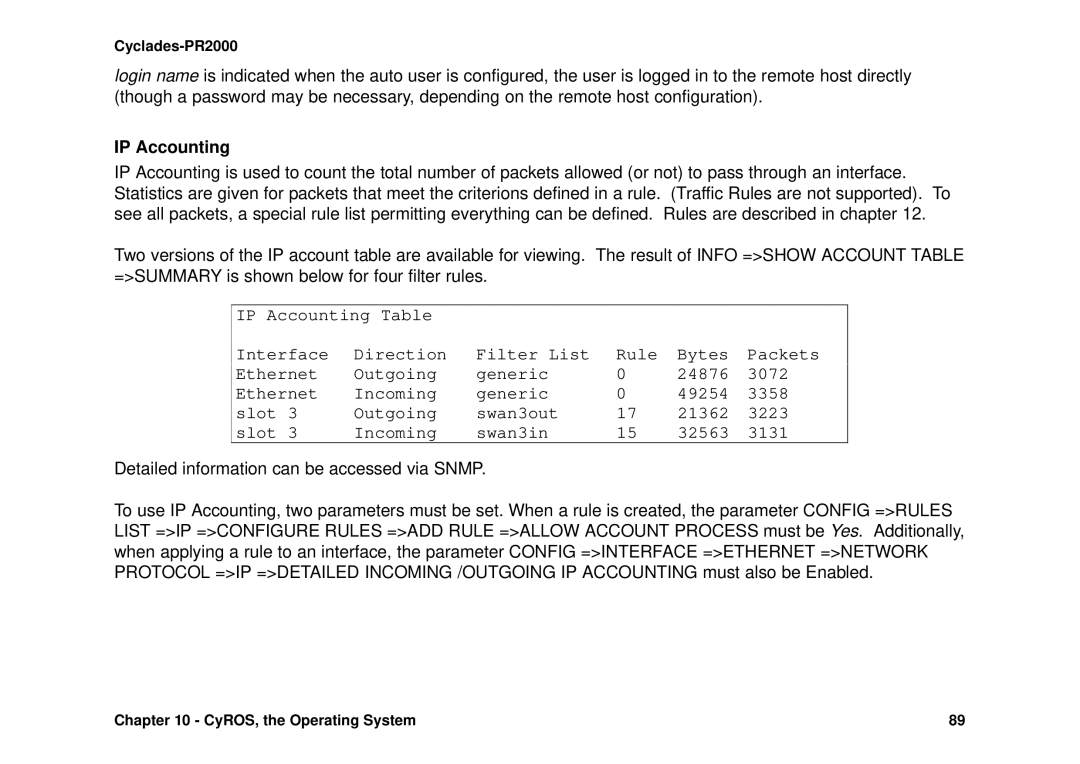
Two versions of the IP account table are available for viewing. The result of INFO =>SHOW ACCOUNT TABLE =>SUMMARY is shown below for four filter rules.
IP Accounting Table
Interface | Direction | Filter List | Rule | Bytes | Packets | |
Ethernet | Outgoing | generic | 0 | 24876 | 3072 | |
Ethernet | Incoming | generic | 0 | 49254 | 3358 | |
slot | 3 | Outgoing | swan3out | 17 | 21362 | 3223 |
slot | 3 | Incoming | swan3in | 15 | 32563 | 3131 |
Detailed information can be accessed via SNMP.
To use IP Accounting, two parameters must be set. When a rule is created, the parameter CONFIG =>RULES LIST =>IP =>CONFIGURE RULES =>ADD RULE =>ALLOW ACCOUNT PROCESS must be Yes. Additionally, when applying a rule to an interface, the parameter CONFIG =>INTERFACE =>ETHERNET =>NETWORK PROTOCOL =>IP =>DETAILED INCOMING /OUTGOING IP ACCOUNTING must also be Enabled.
Chapter 10 - CyROS, the Operating System | 89 |