How to install
<Fig. 2> | <Fig. 3> |
INSTALLATION MANUAL
for Concealed Duct Type Indoor Unit
MODEL: TCB-DP11BE
1. Installation of drain-up kit body (See Fig. 1.)
Open the cover of
2. Hose connection (See Fig. 1.)
• First connect the drain hose to pipe at the drain port of the drain up kit, |
and then connect it to the drain port of the air conditioner body. |
Tighten the both ends of the drain hose with hose band. In this time, be |
P.C. board
To drain up
Cable
CN030
(RED)
CN068 CN030
(BLUE) (RED)
3 | 1 | 3 | 1 |
3 | 1 | 3 | 1 |
Drain pump
(DP)
Float switch
(FS)
WARNING
•Ask the qualified installation professional to install the drain up kit.
If drain up kit is inappropriate installed by yourself, it may cause a water leak, an electric shock fire and so on.
•Install the drain up kit surely according to this installation manual.
•When
If drain up kit is installed by yourself, it may cause a water leak, an electric shock fire and so on.
Configuration
| sure to set the screw section of the hose band toward upper side. |
• | Apply thermal insulation the drain hose with the attached thermal |
| insulation pipe. |
| Set the both ends of the drain hose closely to the drain pan. |
• | If a gap is generated on the matched section of the thermal insulation |
| materials at the both ends, seal the section by winding the thermal |
| insulation tape. |
3. Drain piping
•Be sure to set the drain pipe from the drain up kit with falling gradient. Support and fix the drain pipe at an appropriate position so that an excessive load is not applied on the drain port.
•Be sure to apply thermal insulation (procured locally) to the drain pipe.
<Fig. 1> | Air conditioner body | Drain up kit |
Arrange the cables so that they do not apply
a tension upon the
CN068 (BLUE)
Test run
Condition check of water drain
After the electric work and cabling work, check the drain is smoothly discharged by running the air conditioner in COOL mode.
•If the cooling operation does not continue for a long time, pour water into the drain pan of the air conditioner body to check whether the drain is smoothly discharged or not.
•Check there is no water leak at each connecting section.
– 174 –
| Name | Q’ty |
| Name | Q’ty |
A | Drain up kit body | 1 | E | Bundling band | 3 |
B | Drain hose | 1 | F | Tapping screw | 4 |
C | Hose band | 2 | G | Thermal insulation tape | 2 |
D | Thermal insulation pipe | 1 |
|
|
|
Drain outlet
Discharge ![]()
![]() duct
duct ![]()
![]()
Check lid
30 | Mounting screws | |
(4 pcs.) | ||
| ||
|
|
Electric
![]() parts box
parts box
Cable
Operation check of float switch
•During cooling operation, operate the float switch.
Check the air conditioner stops the cooling operation under condition that the drain pump keeps operating.
•After operation in COOL mode, operate the float switch.
In this time, check that the drain pump works to discharge the drain.
CD
AB
EF
Drain pan (Drain port)
Drain hose,
thermal insulation pipe
Drain inlet (Drain port)
Suction panel
<Position of float switch>
Float switch |
35 |
•To handle the float switch, remove the front panel of the kit and push up the floating section of the float switch with a screwdriver, etc.
•Be careful not to operate the float switch consecutively for 2 minutes or more because the air conditioner stops abnormally.
G
REQUIREMENT
•Be sure to install the drain up kit correctly according to the procedure described in this Installation Manual. Otherwise, the position of the drain pan on the drain up kit does not match with one on the air conditioner body, resulting in a water leak.
•Check the level of the air conditioner.
(Check that it is horizontally set or the drain port side of the air conditioner is set with an inclination within 1˚ downward.)
•Be sure to make a check port to the lower ceiling part of the drain up kit.
*Using the hose band, tighten the drain port and drain inlet of the drain pan. Also, be sure to set the screw section of the hose band toward upper side.
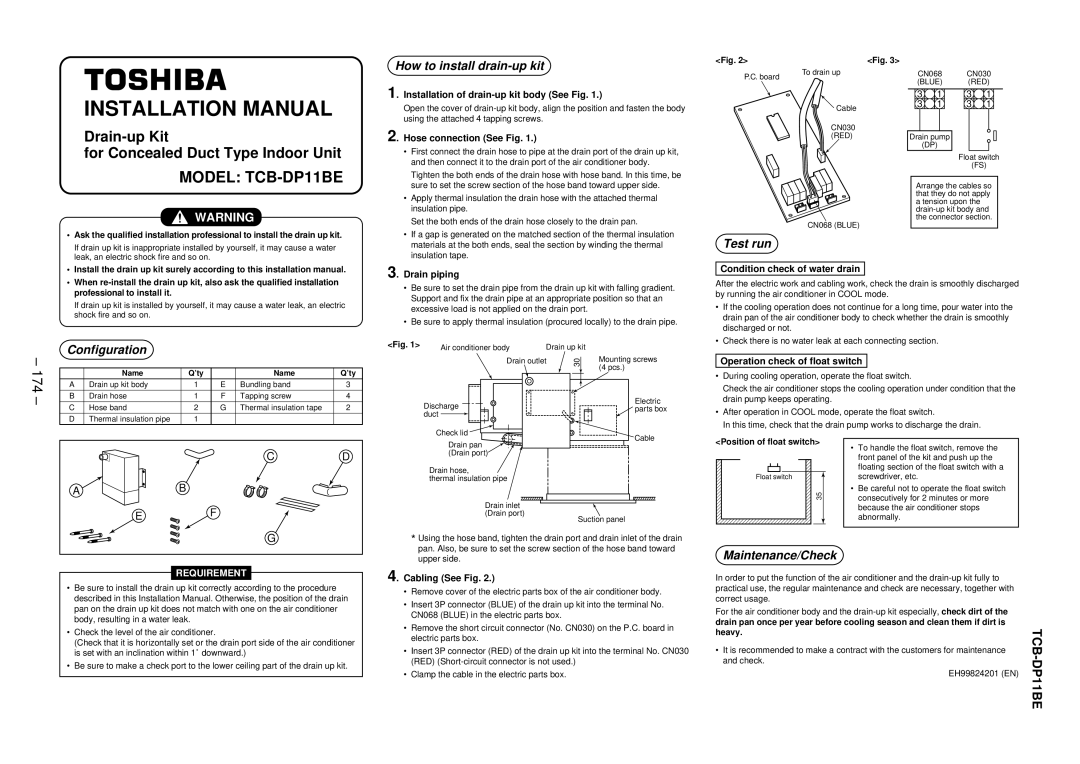
4. Cabling (See Fig. 2.)
•Remove cover of the electric parts box of the air conditioner body.
•Insert 3P connector (BLUE) of the drain up kit into the terminal No. CN068 (BLUE) in the electric parts box.
•Remove the short circuit connector (No. CN030) on the P.C. board in electric parts box.
•Insert 3P connector (RED) of the drain up kit into the terminal No. CN030 (RED)
•Clamp the cable in the electric parts box.
Maintenance/Check
In order to put the function of the air conditioner and the
For the air conditioner body and the
•It is recommended to make a contract with the customers for maintenance and check.
EH99824201 (EN)