Split Type
Type Indoor unit Outdoor unit
DC motor AC motor
Name 0BT-E ∗∗ 1BT-E
∗∗ 1CT-E
Contents
Installation Manual
Outdoor
Precautions for Safety
New Refrigerant Air Conditioner Installation
To Disconnect the Appliance from Main Power Supply
RAV-SP1100, 1400AT-E RAV-SM1100, 1400AT-E
Refrigerant Piping
Accessory and Refrigerant
Accessory and Installation Parts
Selection of Installation
Before installation
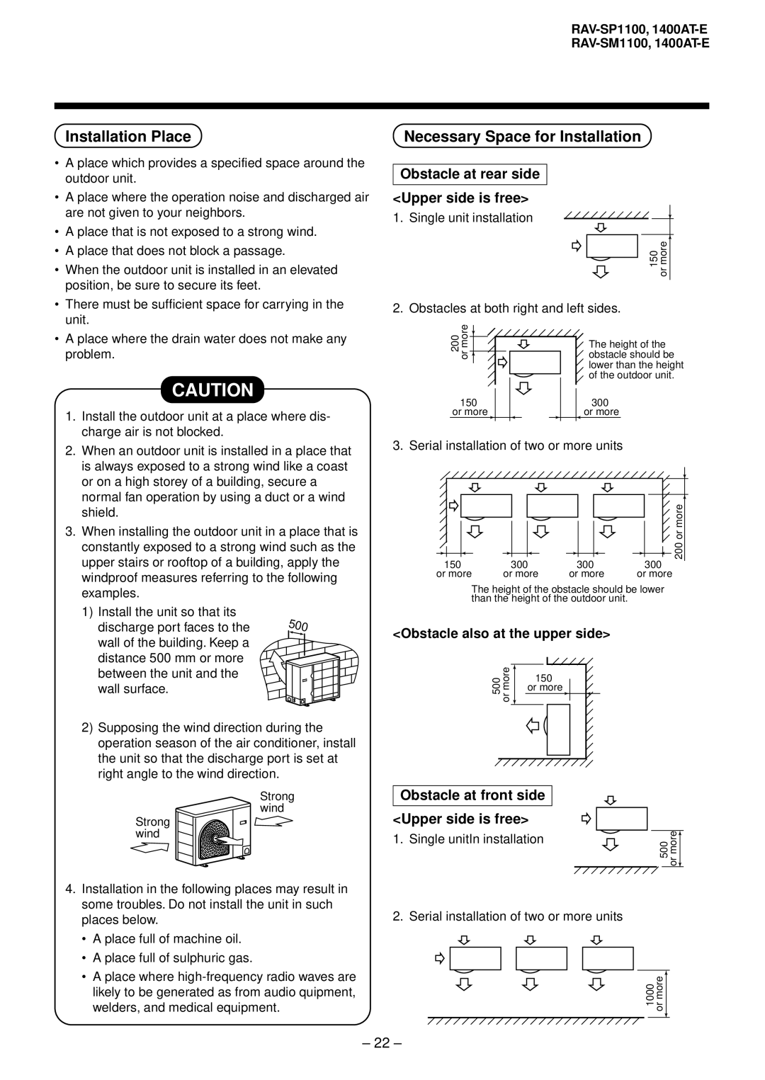
Installation Place
Necessary Space for Installation
Obstacle at rear side Upper side is free
Obstacle at front side Upper side is free
Installation of Outdoor Unit
Standard installation
Serial installation at front and rear sides
Obstacle also at the upper side
Optional Installation Parts Local Procure
Refrigerant Piping Connection
For Reference
Knockout of Pipe Cover
Refrigerant Piping
Pipe Forming/End Positioning
Tightening of Connecting Part
Outer dia. of copper pipe Tightening torque
Vacuum pump
Evacuating
Air Purge
Charge port
How to open the valve
Valve size
Electrical Work
Stripping length power cord and connecting cable
How to wire
Self-Diagnosis by LED Indication
Final Installation Checks
Check and Test Operation
New tools for R410A Applicable to R22 model Changes
Changes in the product and components
New tools for R410A
Indoor
Part name ’ty Shape Standard wired remote Controller
Separate sold parts
RAV-SM560, 561, 800, 801BT-E RAV-SM1101, 1401BT-E
Part name ’ty Shape
Connect the connecting cable correctly
Inappropriate grounding may cause electric shock
Selection of Installation Place
Installation space Selection of installation place
Advice
Secure the space required to installation and servicing
Installation of Indoor Unit
Installation procedure
Dimension
External view
100
RAV-SM1101, 1401BT
Installation of remote controller Sold separately
Mounting of clamp Accessory
Hanging down of indoor unit
Clamp mounting Removal of air filter
Restriction to installation
Installation clearance
Concealed duct type
Ledge ceiling concealed duct type
103
Static pressure characteristics of each model
AIR Ducting Work
RAV-SM1101BT Round duct
RAV-SM1401BT Round duct
Connecting method of the duct
106
Points at installation work
General cautions
Mounting of remote controller
Hanging of indoor unit
Mounting of filter and canvas for suction port
107
Drain Piping Work
Piping material
Piping and cautions
Thermal-insulating process
Drain-up
Connection of the drain hose
Check of water drain
After electric piping work
Permissible piping length and heat
Flaring dia meter size a Unit mm
Tightening connection
Tightening torque of flare pipe connections
Packed valve handling precautions
Open valve fully
Gas leak check
Use a vacuum pump
112
For 801, 1101, 1401AT model
801, 1101, 1401 type valve at gas side
113
Remote controller cabling
Cabling diagram
Cabling
114
How to execute a test run
Case of wired remote controller
Test RUN
Before test run
Troubleshooting
Confirmation of error history
Procedure Description
Confirmation and check
117
Applicable Controls
Automatic address
Setup of external static pressure
When using wireless remote controller
To incorporate a filter sold separately
Short plug position CN112, CN111, CN110 from the left
119
Change of lighting time of filter sign
To secure better effect of heating
INSTALLATION/SERVICING Tools
Maintenance
Cleaning of Return grille
Clean the Return grilles with water
121
RAV-SM561, 801CT-E RAV-SM1101, 1401CT-E
Part name ’ty Shape Usage
Part name
122
123
124
Installation space
Avoid installing in the following places
Case of wireless type
Height of ceiling
How to use attached installation pattern
126
Model name 561CT
801CT
Installation of hanging bolts
Knockout hole of power cable take-in port
Pipe knockout hole
Draw-out direction of pipe/cable
Installation of indoor unit
Piping/Heat insulating material
Drain up
Collective piping
Adhesive inhibited
Connection of drain hose Thermal insulating process
Connection of drain pipe
Case of taking pipe from the left side
130
Refrigerant Piping and Evacuating
Flaring diam. meter size a Unit mm
131
Outer diam. of copper pipe
Piping with outdoor unit
Open the valve fully
Refrigerant amount to be added
Gas leak check
133
Be sure to connect earth wire. Grounding work
Remote controller wiring
Cable connection
134
Wiring diagram
135
136
137
138
Case of installation to high ceiling
139
Set data 0000
Set data
140
Tools
Removal of suction grille
141
Cleaning of air filter
Accessories
RBC-EXW21E
144
Operation procedure
Program button Cancel button
Timer set button
Holiday setting indication mark
146
147
148
RBC-AS21E
149
Automatic Cool/Heat
150
AS21E
RBC-AX22CE
151
152
Remote Controller
Signal Receiving Part
153
Operation Section Display Section
154
155
To Use the Remote Controller Setting to Wall, etc
How to Check the Address
How to Match the Address
When a signalis correctlyreceived, Pisoundcan be heard
157
Start
Phenomenon Cause Measures
Phenomenon Cause
158
Accessory parts
Requirement for installation Multiple remote controllers
Remote controller test run setup
How to perform cabling of the remote controller
Program Weekly Timer
160
Accessory parts
Requirement to install the remote sensor
How to install the remote sensor
161
162
Installation of sensor unit
Accessory
How to perform cabling of sensor units
How to set the room temperature sensor
How to set the address switch
Slide switch
How to set up filter sold separately of the high ceiling
How to handle the remote controller
164
Test run
To Personnel Charged in Installation Work and Service
Never modify or repair the product
Ceiling panel
’ty ØM5mm x 40mm ØM4mm x 12mm
Flap
Installation of adjust corner cap
Installation of suction grille
Check after installation
For wireless remote controller
TCB-DP22CE
168
Connect the connecting cable correctly
New Refrigerant Air Conditioner Installation
To Disconnect the Appliance from Main Power Supply
169
Before installation
170
Knockout hole
Connection of Elbow Piping KIT
How to install drain up kit
171
Thermal insulating process
Tightening connection
172
Connection of drain hose at indoor unit side
Connection of drain hose at drain up kit side
Piping/Heat insulating material
173
Check the draining
174
For Installation Professionals
175
Use for Indoor Unit Only
Combination List of Adapter Parts
Case of Concealed Duct RAV-SM **0 BT-E
176
Case of 4-way Ceiling Cassette RAV-SM **0 UT-E
Address No. setup table SW01
Procedure
Setup from the remote controller at the indoor unit side
Setup by the switch on the adapter P.C. board
178
To Customers
TCB-KP12CE TCB-KP22CE
179
Parts List
180
181
Installation of high-efficiency filter
Setup of fan when building in the high-efficiency filter
182
High-Efficiency Filter
Deodorant Filter, Ammonium Filter
Setup of fan when building in the filter sold separately
183
Page
Memo