Setup of the Address No.
To connect the indoor unit to the central remote controller using the adapter, it is necessary to set up the network address No.
•It is required to agree the network address No. with the central remote controller system No.
•The network address No. is set to 1 at the shipment from the factory.
The following two methods are used for setup.
1.Setup from the remote controller at the indoor unit side
• This method is available only when [7] of the setup switch SW01 on the adapter P.C. board is OFF.
<Procedure> Set up the address No. while the air conditioner stops.
1 Push  and
and  buttons for 4 seconds or more.
In case of the group control, the unit No. ALL is displayed, and then all the indoor units in the group control are selected. (Fig. 1)
In this time, the fans of all the selected indoor units start and the swing operation also starts in the models with flaps. (Keep the display status of ALL without pushing UNIT button.)
In case of individual remote controller with no group control, the system address and the indoor unit address are displayed.
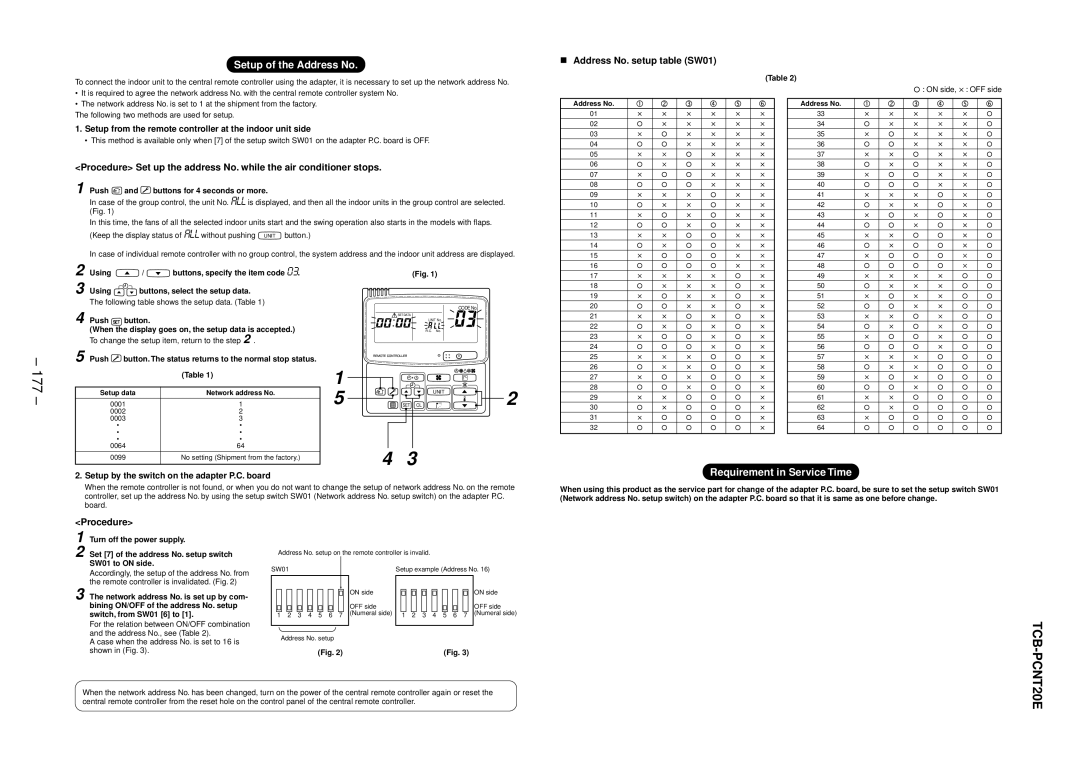
Address No. setup table (SW01)
Address No.
01
02
03
04
05
06
07
08
09
10
11
12
13
14
15
(Table 2)
![]() : ON side,
: ON side, ![]() : OFF side
: OFF side
Address No.
33
34
35
36
37
38
39
40
41
42
43
44
45
46
47
– 177 –
2 Using ![]() /
/ ![]() buttons, specify the item code 03.
buttons, specify the item code 03.
3 Using ![]() buttons, select the setup data.
buttons, select the setup data.
The following table shows the setup data. (Table 1)
4 Push SET button.
(When the display goes on, the setup data is accepted.)
To change the setup item, return to the step 2 .
5 Push  button. The status returns to the normal stop status.
| (Table 1) |
|
|
Setup data | Network address No. |
0001 | 1 |
0002 | 2 |
0003 | 3 |
• | • |
• | • |
• | • |
0064 | 64 |
0099 | No setting (Shipment from the factory.) |
|
|
1
5
(Fig. 1)
CODE No.
![]() SET DATA
SET DATA
UNIT No.
R.C. No.
| UNIT | 2 |
SET CL |
|
4 3
16
17
18
19
20
21
22
23
24
25
26
27
28
29
30
31
32
48
49
50
51
52
53
54
55
56
57
58
59
60
61
62
63
64
2. Setup by the switch on the adapter P.C. board
Requirement in Service Time
When the remote controller is not found, or when you do not want to change the setup of network address No. on the remote controller, set up the address No. by using the setup switch SW01 (Network address No. setup switch) on the adapter P.C. board.
When using this product as the service part for change of the adapter P.C. board, be sure to set the setup switch SW01 (Network address No. setup switch) on the adapter P.C. board so that it is same as one before change.
<Procedure>
1 Turn off the power supply.
2 Set [7] of the address No. setup switch SW01 to ON side.
Address No. setup on the remote controller is invalid.
Accordingly, the setup of the address No. from the remote controller is invalidated. (Fig. 2)
3 The network address No. is set up by com- bining ON/OFF of the address No. setup switch, from SW01 [6] to [1].
For the relation between ON/OFF combination and the address No., see (Table 2).
A case when the address No. is set to 16 is
SW01
1 2 3 4 5 6 7
Address No. setup
Setup example (Address No. 16)
ON side |
|
|
|
|
|
|
|
|
|
|
|
|
|
|
| ON side |
|
|
|
|
|
|
|
|
|
|
|
|
|
|
| ||
OFF side |
|
|
|
|
|
|
|
|
|
|
|
|
|
|
| OFF side |
(Numeral side) |
|
|
|
|
|
|
|
|
|
|
|
|
|
|
| (Numeral side) |
1 | 2 | 3 | 4 | 5 | 6 | 7 |
| |||||||||
|
|
| ||||||||||||||
|
|
|
|
|
|
|
|
|
|
|
|
|
|
|
|
|
TCB
shown in (Fig. 3).
(Fig. 2) | (Fig. 3) |
-PCNT20E
When the network address No. has been changed, turn on the power of the central remote controller again or reset the central remote controller from the reset hole on the control panel of the central remote controller.