LinStep+ Dual-Axis Microstepping Indexer/Driver
Table of Contents
Arithmetic Operands and Equations
Other Programming Samples Ii Table of Contents MN1854
Increment/Decrement Variables
Troubleshooting Serial Communications Problems
Iv Table of Contents MN1854
Section General Information
Limited Warranty
CE Compliance
Product Notice Intended use
Could result in injury or death
Could result in damage to property
On next 2General Information MN1854
Do not touch any circuit board, power device or electrical
Connection before you first ensure that power has been
Do not apply AC power before you ensure that grounds are
Voltages that are conducted to its power input terminals.
Extend more than 0.2 5 into keypad assembly
Instead, we recommend using a four wire Wye
Power is removed from the drive
Driver should have specifications compatible to the drive
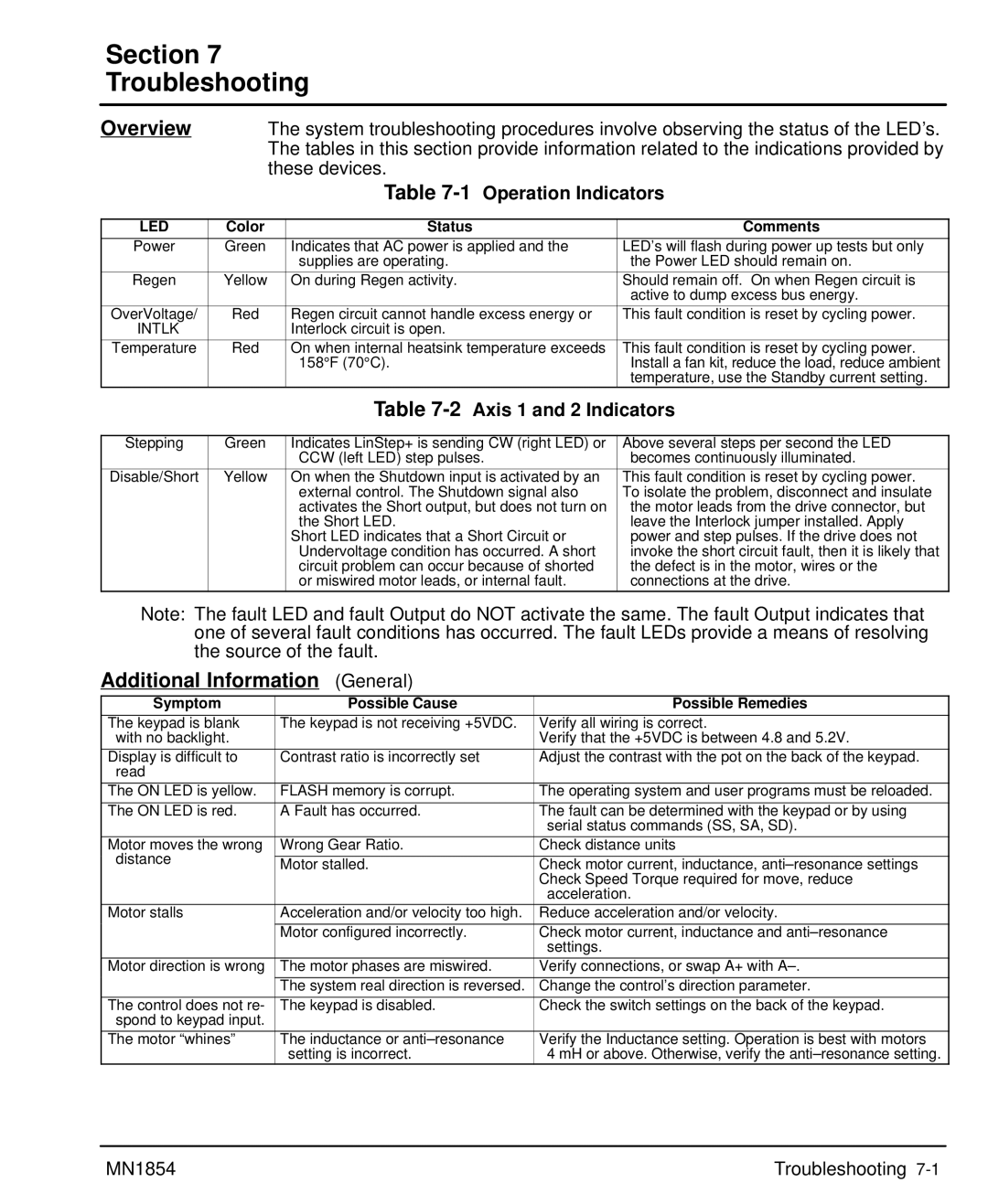
Overview
Section Product Overview
Motors
Product Overview MN1854
Section Receiving and Installation
Power Dissipation
Mechanical Installation
Receiving & Inspection
2Receiving & Installation MN1854
GND
Input Power Conditioning
System Grounding Ungrounded Distribution System
Power Connections Power connections are shown in Figure
Wire Size and Protection Devices
4Receiving & Installation MN1854
MN1854 Receiving & Installation
Connection Locations 115VAC, 2 Axis
6Receiving & Installation MN1854
Tools Required
9 & 25 Pin RS-232 Cable Connections for UL Installations
RS-232 PC Connections
8Receiving & Installation MN1854
Daisy Chain Connections
Rules for Daisy Chain Operation
PC / Host Device
Programmable I/O Connections
Optional Opto I/O Connections
These input connections are made at terminals 6-40 Figure
Typical connection each input
10Receiving & Installation MN1854
Encoder Signal PVS100 Danaher 9-Pin D
Encoder Color Code
+5VDC
Motor Connector
LD9068A00 Leadwire Connection 9 pin to flying leads
Interlock Intlk
Ground GND
Start-Up Procedure
Power Off Checks
Switch and Potentiometer Settings
Section General Information
Power On Checks
Action Display Comments
Motor should now be producing torque
High
Receiving & Installation MN1854
Section Keypad Operation
Overview
Keypad layout with the LCD display is shown in Figure
F1, F2, F3
Copies one program to another within the LinStep+
Comma
Decimal Point
Alpha
Test
Thus eliminating the need for a PC terminal connection
Trace Output Move
Shutdn RS232 Encoder
Edit Menu
Pressing the Edit key displays a set of sub-menus
Save the program
Edit an existing program
6Keypad Operation MN1854
Save Program? YesNo
Naming a program
Example of Naming a Program
Press ESC. You will be prompted as shown in Figure
Mine AC.3 VE2 DI1 GO
Use the =O keys for additional alpha characters
Entering Characters with the Alpha Key In edit mode
8Keypad Operation MN1854
Edit, Setup Submenu
Submenu Setup Parameter Description of Setup Parameter
Press EDIT, POS F3 Press YES F1 or no F3
Press EDIT, ↓ , List to
Display the number
Programs stored Press ↓ to display the total
Pressing Help in the Main Menu
Pressing Help in Menus and Sub-Menus
Pressing Help In the Program Edit function
Sequentially Eeprom message disappears
COPY, to PAD Submenu
Enter the program number. Or, if
You wish, you can scroll the list
Program names
Section Setup
Procedure Format Definition
Setup MN1854
Axis One Motor Type Steper
Axis One Drive Res
Axis One Motor Dir
Axis One ENC Mode
Open Loop
Application Notes
Axis One Encoder RES ↑5000 cnts/in ↓
IN-RANGE Setup Window
Value
IN-RANGE Window
PM Gain
Configure Your Application Mechanics
Mech Setup
Dist
Vmax Accel Amax
Axis One Vel Units In/s
Edit
Axis One MAX Vel
500.0 in/s ↓→
Iuuuuuuu ←↑↓→
Configure the I/O
Char Keypad Display Input Character Description
Inputs will work. See the RG command for more details
Service routine program
To summarize, when INT98CTRL=1
Reset to 1. This allows for input debounce and controlling
Warm Boot
Power-up program, if defined, will start
Jog Speed
Inputs
OUT1 Programmable Pppppppp ←↑↓→
Configure the Output States
OPTO9 Input
Iiiiiiii
OFF
Configure End of Travel Switch Polarity
Configure JOG Parameters
Enable
Accel LO-VEL HI-VEL
Mode Edge Switch
Configure Home Parameters
Offset DIR
Negative
Configure Power-up Program
↑SETUP↓
Power Up Program PROGRAM0
Axis One Final Dir Positive
Configure Serial Communications
RS232C Setup
↑ Enabled ↓
Echo UNIT#
Configure Miscellaneous Setup Parameters
Data Type Description of Display Data Type
General Password Rules
Password Setup
Opratr Admin Clear
Password Type Description Gives access to these menus
Keypad Program Command List
Section Keypad Programming
Acceleration Start Home Outputs On/Off
Function Key Message to Display
Keypad Programming MN1854
Value Units Range
Example
AC2 DE.5 VE12 DA3 GO DA3 GO DA3 GO
DC Distance to Change
Example Distance to Change
DCn * DCn*1 * Vn*1 2* Vnt w
Examples of DC move profiles, AC = seconds, VE=ips
DC n + 10 +
DE Deceleration
AC.1 VE60 DI2 GO DI1 GO DI-4 GO
LP2 DI3 GO EB
Value Units Range N/A
IF2,1 EN EB DI2 GO
=12 =13 =17 =18 =22 =23
=26 =27 =28
RUN Edit
Copy DEL
Example 3-Screen Menu Program
Set in Edit Setup Mech Accel VEL
GH Start Home
Go Immediate Syntax GI or GIi
Value N/A Units N/A Range N/A
GO Go Start a Move Syntax GO or GOi
Value N/A Units N/A Range i=1-16
AC.05 DE.05 VE50 DI5 GO
VE2 AC.1 DA4,2 GP
Gosub Syntax GSi and GSname
=1-400, name = any legal program name
IF10 Gtpart a EB
If input 1 is on and input 2 is off, jump to program Part a
Units Range
IFPARTS=25 GS20 EB
Lppieces
IV12,LENGTH
Dilength
Syntax LPi LP Loop
Value Units N/A Range N/A
Syntax MC+ MC Move Continuous
Move Continuous
MS27,COUNT
27 7th character, 2nd row
Powerup ONL,GTON EOT
Gthome
Main
VE5 DA20 GO
= starting output number
=0 input high. X=1 input low grounded
=anything else ignore input changes
OT4,1 Turn on Output OT2,0D1
Syntax RGr RG Registration
SQRESULT=0 SQ27.96,SQRESULT
Value N/A Units N/A
ST1 AC1 DE1 VE25 DA6 GO VE50 DA0 GO EN
Value N/A Units seconds
WTexpression
Syntax VEr VE Velocity
= starting input number
Helpful Hints Programming your application
Summary of Expressions, Operators and Functions
Programming Overview
Program
Example of Hosted Mode
Variable Names
Built-in Variables
Examples of how to use Built-in Variables
Variable Name Description of Built-in Variable Type
Using Built-in Variable Arowrel
Parts
Non-Volatile Variables
Lpnumber
AO15=VOLTAGE + Error
Arithmetic Operands and Equations
Examples of incorrect use
Instead, you should use
Logical Operators
Increment/Decrement Variables
Expressions
Other Programming Samples
Create a Message and Read an Input Variable
Setting an Output=On on-the-fly
Create a Menu menu display on keypad display for operator
Read a 4 Digit BCD number, 2 Digits at a time
Reading an Analog Input Value
GET 4 Bcds
Digit BCD=4 Digit BCD+2TW
Section Troubleshooting
1Operation Indicators
2Axis 1 and 2 Indicators
Additional Information General
Troubleshooting MN1854
Additional Information
Serial Communications Problems
Troubleshooting MN1854
Section Specifications & Product Data
MN1854 Specifications & Product Data
Identification
LinStep+ LX 2 P 1 a
General Specifications
Protection & Indicators Description
VAC
VDC
Optional Keypad 10.08 256.0 Axis Driver 148.3
Dimensions
94.7 230.1
Specifications & Product Data MN1854
Wiring of Shielded Screened Cables
Section CE Guidelines
CE Declaration of Conformity
EMC Conformity and CE Marking
EMC Wiring Technique
CE Guidelines MN1854
Cit
Grounding Earth
EMC Installation Instructions
Cable Screens Grounding
Input Signal Cable Grounding
Simulated Encoder Output Cable Grounding
Encoder Cable Grounding
To Controller
Programming Template
Appendix a
MN1854 Appendix A-1
Appendix MN1854
MN1854 Appendix A-3
Remote Keypad Mounting Template
122.88
838
111.25
Baldor Electric Company
Baldor Electric Company MN1854 01 C&J
LinStep+ Dual-Axis Microstepping Indexer/Driver