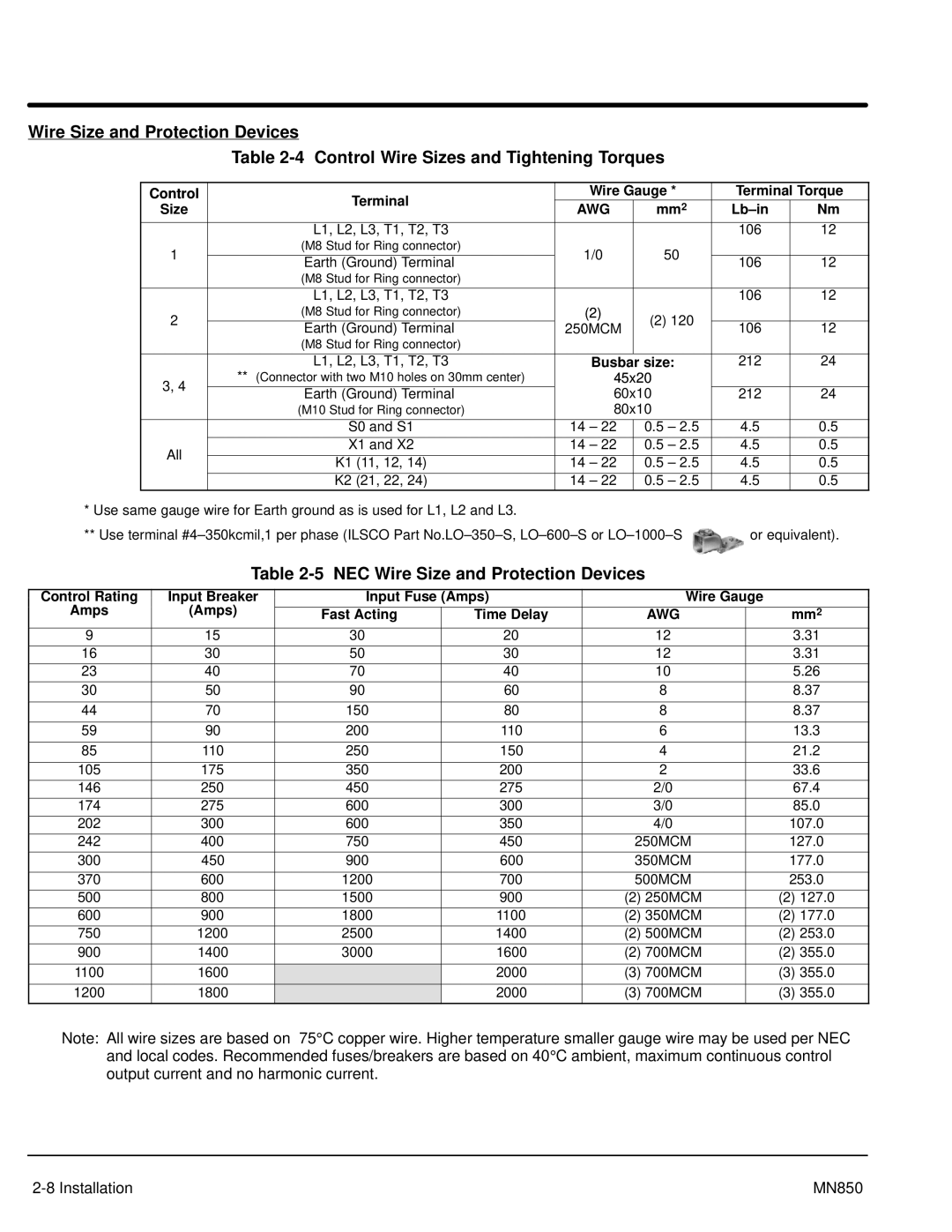
Wire Size and Protection Devices
Table
Control | Terminal | Wire Gauge * | Terminal Torque | |||
Size | AWG | mm2 |
| Nm | ||
| ||||||
| L1, L2, L3, T1, T2, T3 |
|
| 106 | 12 | |
1 | (M8 Stud for Ring connector) | 1/0 | 50 |
|
| |
|
|
| ||||
Earth (Ground) Terminal | 106 | 12 | ||||
|
|
| ||||
| (M8 Stud for Ring connector) |
|
|
|
| |
|
|
|
|
|
| |
| L1, L2, L3, T1, T2, T3 |
|
| 106 | 12 | |
2 | (M8 Stud for Ring connector) | (2) | (2) 120 |
|
| |
Earth (Ground) Terminal | 250MCM | 106 | 12 | |||
|
| |||||
| (M8 Stud for Ring connector) |
|
|
|
| |
|
|
|
|
|
| |
| L1, L2, L3, T1, T2, T3 | Busbar | size: | 212 | 24 | |
3, 4 | ** (Connector with two M10 holes on 30mm center) | 45x20 |
|
| ||
Earth (Ground) Terminal | 60x10 | 212 | 24 | |||
| ||||||
| (M10 Stud for Ring connector) | 80x10 |
|
| ||
|
|
|
|
|
| |
| S0 and S1 | 14 – 22 | 0.5 – 2.5 | 4.5 | 0.5 | |
All | X1 and X2 | 14 – 22 | 0.5 – 2.5 | 4.5 | 0.5 | |
K1 (11, 12, 14) | 14 – 22 | 0.5 – 2.5 | 4.5 | 0.5 | ||
| ||||||
| K2 (21, 22, 24) | 14 – 22 | 0.5 – 2.5 | 4.5 | 0.5 | |
*Use same gauge wire for Earth ground as is used for L1, L2 and L3.
**Use terminal ![]() or equivalent).
or equivalent).
Table 2-5 NEC Wire Size and Protection Devices
Control Rating | Input Breaker | Input Fuse (Amps) | Wire Gauge |
| ||
Amps | (Amps) |
|
|
|
|
|
Fast Acting | Time Delay | AWG |
| mm2 | ||
9 | 15 | 30 | 20 | 12 |
| 3.31 |
16 | 30 | 50 | 30 | 12 |
| 3.31 |
23 | 40 | 70 | 40 | 10 |
| 5.26 |
30 | 50 | 90 | 60 | 8 |
| 8.37 |
|
|
|
|
|
|
|
44 | 70 | 150 | 80 | 8 |
| 8.37 |
|
|
|
|
|
|
|
59 | 90 | 200 | 110 | 6 |
| 13.3 |
|
|
|
|
|
|
|
85 | 110 | 250 | 150 | 4 |
| 21.2 |
|
|
|
|
|
|
|
105 | 175 | 350 | 200 | 2 |
| 33.6 |
146 | 250 | 450 | 275 | 2/0 |
| 67.4 |
174 | 275 | 600 | 300 | 3/0 |
| 85.0 |
202 | 300 | 600 | 350 | 4/0 |
| 107.0 |
242 | 400 | 750 | 450 | 250MCM |
| 127.0 |
300 | 450 | 900 | 600 | 350MCM |
| 177.0 |
|
|
|
|
|
|
|
370 | 600 | 1200 | 700 | 500MCM |
| 253.0 |
500 | 800 | 1500 | 900 | (2) 250MCM |
| (2) 127.0 |
600 | 900 | 1800 | 1100 | (2) 350MCM |
| (2) 177.0 |
750 | 1200 | 2500 | 1400 | (2) 500MCM |
| (2) 253.0 |
900 | 1400 | 3000 | 1600 | (2) 700MCM |
| (2) 355.0 |
|
|
|
|
|
|
|
1100 | 1600 |
| 2000 | (3) 700MCM |
| (3) 355.0 |
1200 | 1800 |
| 2000 | (3) 700MCM |
| (3) 355.0 |
|
|
|
|
|
|
|
Note: All wire sizes are based on 75° C copper wire. Higher temperature smaller gauge wire may be used per NEC and local codes. Recommended fuses/breakers are based on 40° C ambient, maximum continuous control output current and no harmonic current.
MN850 |