Appendix D
Voltage Surge Protection
Grounding | Proper grounding is extremely important. The symptoms produced by improper |
| grounding are obvious. Sometimes filters and other expensive devices are added to |
| reduce the effects of problems caused by poor grounding. There can be several |
| reference points (neutrals) in a circuit but there should always only be one ground point. |
| Neutral and ground are not the same. Neutral should normally be a non current carrying |
| conductor, but it should be sized to carry momentary current caused be short circuits in |
| the equipment. All of the neutrals in a system should connect at a central point and that |
| point should be connected to the system ground. |
| The goal is to minimize the current through the ground conductor. Circulating ground |
| current is a source of electrical noise normally associated with unbalanced voltages or |
| unbalanced loads. Capacitive or inductive coupling between power lines and the neutral |
| or ground conductors is another noise source. Currents that flow through capacitive |
| paths or from a magnetic field tend to change rapidly and produce high frequency |
| interference called RFI (radio frequency interference). |
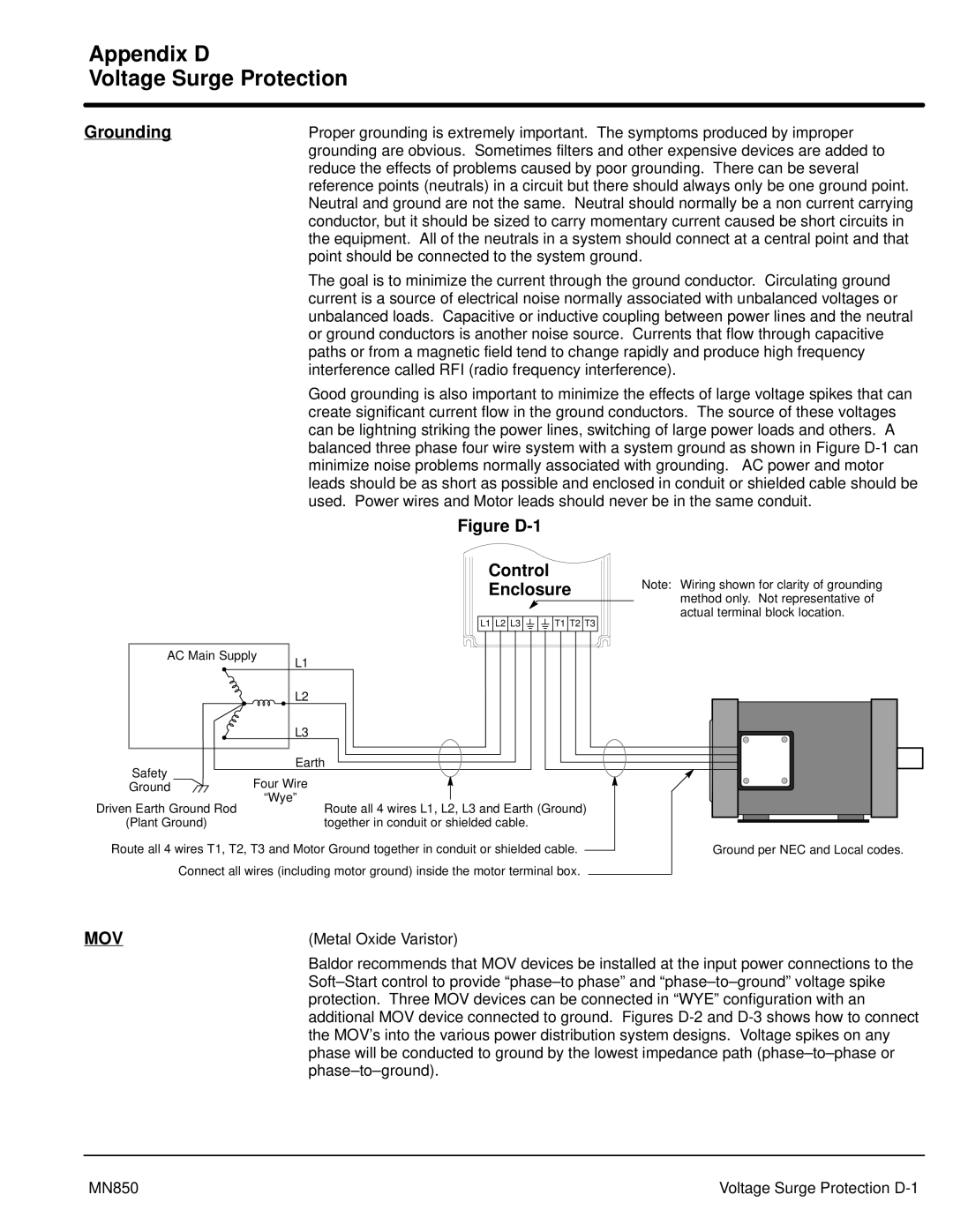
| Good grounding is also important to minimize the effects of large voltage spikes that can |
| create significant current flow in the ground conductors. The source of these voltages |
| can be lightning striking the power lines, switching of large power loads and others. A |
| balanced three phase four wire system with a system ground as shown in Figure |
| minimize noise problems normally associated with grounding. AC power and motor |
| leads should be as short as possible and enclosed in conduit or shielded cable should be |
| used. Power wires and Motor leads should never be in the same conduit. |
Figure D-1
|
| Control |
| Note: Wiring shown for clarity of grounding |
|
| Enclosure | ||
|
| method only. Not representative of | ||
|
|
|
| |
|
| L1 L2 L3 | T1 T2 T3 | actual terminal block location. |
|
|
| ||
AC Main Supply | L1 |
|
| |
|
|
|
| |
|
| L2 |
|
|
|
| L3 |
|
|
Safety |
| Earth |
|
|
Four Wire |
|
| ||
Ground |
|
| ||
|
| “Wye” |
|
|
Driven Earth Ground Rod | Route all 4 wires L1, L2, L3 and Earth (Ground) |
(Plant Ground) | together in conduit or shielded cable. |
Route all 4 wires T1, T2, T3 and Motor Ground together in conduit or shielded cable.
Connect all wires (including motor ground) inside the motor terminal box.
Ground per NEC and Local codes.
MOV | (Metal Oxide Varistor) |
| Baldor recommends that MOV devices be installed at the input power connections to the |
| |
| protection. Three MOV devices can be connected in “WYE” configuration with an |
| additional MOV device connected to ground. Figures |
| the MOV’s into the various power distribution system designs. Voltage spikes on any |
| phase will be conducted to ground by the lowest impedance path |
|
MN850 | Voltage Surge Protection |