|
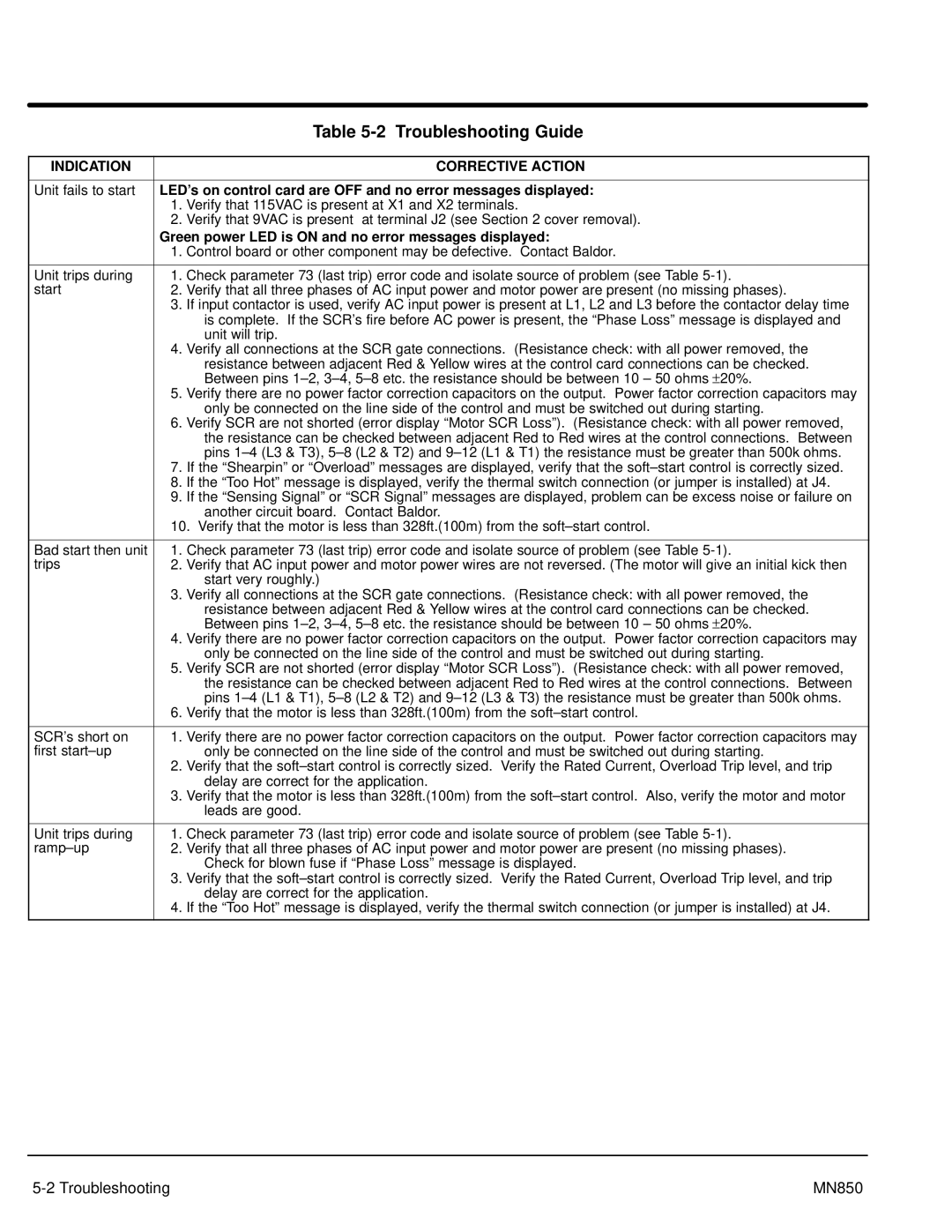
| Table |
|
|
|
INDICATION |
| CORRECTIVE ACTION |
|
| |
Unit fails to start | LED’s on control card are OFF and no error messages displayed: | |
| 1. | Verify that 115VAC is present at X1 and X2 terminals. |
| 2. | Verify that 9VAC is present at terminal J2 (see Section 2 cover removal). |
| Green power LED is ON and no error messages displayed: | |
| 1. | Control board or other component may be defective. Contact Baldor. |
|
| |
Unit trips during | 1. Check parameter 73 (last trip) error code and isolate source of problem (see Table | |
start | 2. Verify that all three phases of AC input power and motor power are present (no missing phases). | |
| 3. | If input contactor is used, verify AC input power is present at L1, L2 and L3 before the contactor delay time |
|
| is complete. If the SCR’s fire before AC power is present, the “Phase Loss” message is displayed and |
|
| unit will trip. |
| 4. | Verify all connections at the SCR gate connections. (Resistance check: with all power removed, the |
|
| resistance between adjacent Red & Yellow wires at the control card connections can be checked. |
|
| Between pins |
| 5. | Verify there are no power factor correction capacitors on the output. Power factor correction capacitors may |
|
| only be connected on the line side of the control and must be switched out during starting. |
| 6. | Verify SCR are not shorted (error display “Motor SCR Loss”). (Resistance check: with all power removed, |
|
| the resistance can be checked between adjacent Red to Red wires at the control connections. Between |
|
| pins |
| 7. | If the “Shearpin” or “Overload” messages are displayed, verify that the |
| 8. | If the “Too Hot” message is displayed, verify the thermal switch connection (or jumper is installed) at J4. |
| 9. | If the “Sensing Signal” or “SCR Signal” messages are displayed, problem can be excess noise or failure on |
|
| another circuit board. Contact Baldor. |
| 10. Verify that the motor is less than 328ft.(100m) from the | |
|
| |
Bad start then unit | 1. Check parameter 73 (last trip) error code and isolate source of problem (see Table | |
trips | 2. Verify that AC input power and motor power wires are not reversed. (The motor will give an initial kick then | |
|
| start very roughly.) |
| 3. | Verify all connections at the SCR gate connections. (Resistance check: with all power removed, the |
|
| resistance between adjacent Red & Yellow wires at the control card connections can be checked. |
|
| Between pins |
| 4. | Verify there are no power factor correction capacitors on the output. Power factor correction capacitors may |
|
| only be connected on the line side of the control and must be switched out during starting. |
| 5. | Verify SCR are not shorted (error display “Motor SCR Loss”). (Resistance check: with all power removed, |
|
| the resistance can be checked between adjacent Red to Red wires at the control connections. Between |
|
| pins |
| 6. | Verify that the motor is less than 328ft.(100m) from the |
|
| |
SCR’s short on | 1. Verify there are no power factor correction capacitors on the output. Power factor correction capacitors may | |
first |
| only be connected on the line side of the control and must be switched out during starting. |
| 2. | Verify that the |
|
| delay are correct for the application. |
| 3. | Verify that the motor is less than 328ft.(100m) from the |
|
| leads are good. |
|
| |
Unit trips during | 1. Check parameter 73 (last trip) error code and isolate source of problem (see Table | |
2. Verify that all three phases of AC input power and motor power are present (no missing phases). | ||
|
| Check for blown fuse if “Phase Loss” message is displayed. |
| 3. | Verify that the |
|
| delay are correct for the application. |
| 4. | If the “Too Hot” message is displayed, verify the thermal switch connection (or jumper is installed) at J4. |
|
|
|
MN850 |