Electrical Noise Considerations
All electronic devices are vulnerable to significant electronic interference signals (commonly called “Electrical Noise”). At the lowest level, noise can cause intermittent operating errors or faults. From a circuit standpoint, 5 or 10 millivolts of noise may cause detrimental operation. For example, analog speed and torque inputs are often scaled at 5 to 10VDC maximum with a typical resolution of one part in 1,000. Thus, noise of only 5 mV represents a substantial error.
At the extreme level, significant noise can cause damage to the drive. Therefore, it is advisable to prevent noise generation and to follow wiring practices that prevent noise generated by other devices from reaching sensitive circuits. In a control, such circuits include inputs for speed, torque, control logic, and speed and position feedback, plus outputs to some indicators and computers.
Relay and Contactor Coils
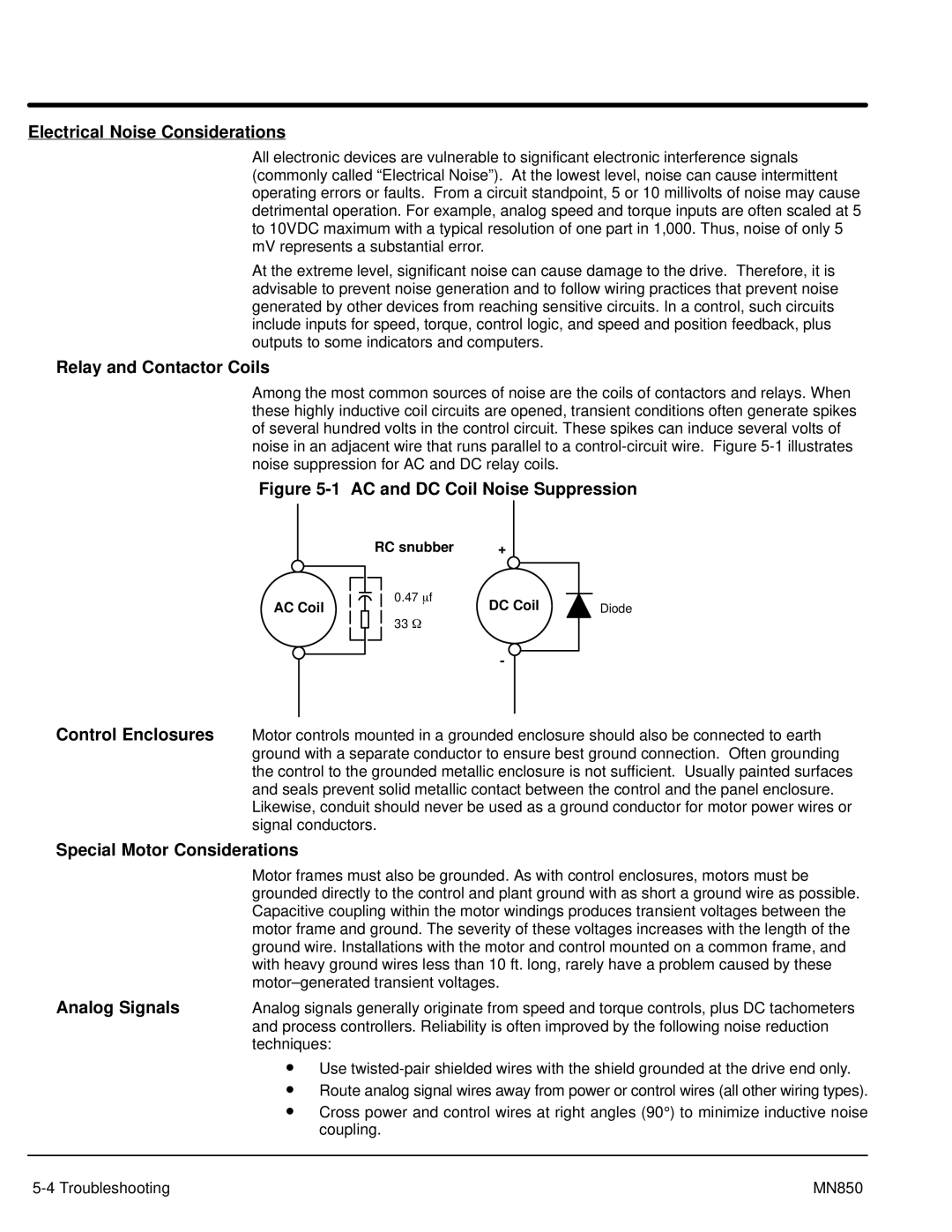
Among the most common sources of noise are the coils of contactors and relays. When these highly inductive coil circuits are opened, transient conditions often generate spikes of several hundred volts in the control circuit. These spikes can induce several volts of noise in an adjacent wire that runs parallel to a
Figure 5-1 AC and DC Coil Noise Suppression
AC Coil
RC snubber | + |
|
0.47 mf | DC Coil | Diode |
|
33W
-
Control Enclosures Motor controls mounted in a grounded enclosure should also be connected to earth ground with a separate conductor to ensure best ground connection. Often grounding the control to the grounded metallic enclosure is not sufficient. Usually painted surfaces and seals prevent solid metallic contact between the control and the panel enclosure. Likewise, conduit should never be used as a ground conductor for motor power wires or signal conductors.
Special Motor Considerations
Motor frames must also be grounded. As with control enclosures, motors must be grounded directly to the control and plant ground with as short a ground wire as possible. Capacitive coupling within the motor windings produces transient voltages between the motor frame and ground. The severity of these voltages increases with the length of the ground wire. Installations with the motor and control mounted on a common frame, and with heavy ground wires less than 10 ft. long, rarely have a problem caused by these
Analog Signals | Analog signals generally originate from speed and torque controls, plus DC tachometers |
| and process controllers. Reliability is often improved by the following noise reduction |
| techniques: |
• Use
• Route analog signal wires away from power or control wires (all other wiring types).
• Cross power and control wires at right angles (90° ) to minimize inductive noise coupling.
MN850 |