Title | P# |
|
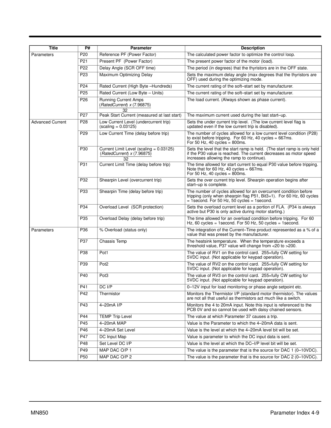
| Parameter | Description | ||
|
|
|
|
|
|
|
|
Parameters | P20 |
| Reference PF (Power Factor) | The calculated power factor to optimize the control loop. | |||
|
|
|
|
|
|
|
|
| P21 |
| Present PF (Power Factor) | The present power factor of the motor (load). | |||
|
|
|
|
|
|
|
|
| P22 |
| Delay Angle (SCR OFF time) | The period (in degrees) that the thyristors are in the OFF state. | |||
|
|
|
|
|
|
|
|
| P23 |
| Maximum Optimizing Delay | Sets the maximum delay angle (max degrees that the thyristors are | |||
|
|
|
|
|
|
| OFF) used during the optimizing mode. |
|
|
|
|
|
|
|
|
| P24 |
| Rated Current (High Byte | The current rating of the | |||
|
|
|
|
|
|
|
|
| P25 |
| Rated Current (Low Byte – Units) | The current rating of the | |||
|
|
|
|
|
|
|
|
| P26 |
| Running Current Amps | The load current. (Always shown as phase current). | |||
|
|
| (RatedCurrent) x (7.96875) |
| |||
|
|
|
|
|
|
|
|
|
| 32 |
|
|
| ||
| P27 |
| Peak Start Current (measured at last start) | The maximum current used during the last | |||
|
|
|
|
|
|
| |
Advanced Current | P28 |
| Low Current Level (undercurrent trip) | Sets the under current trip level. (The low current level flag is | |||
|
|
| (scaling = 0.03125) | updated even if the low current trip is disabled). | |||
|
|
|
|
|
|
| |
| P29 |
| Low Current Time (delay before trip) | The number of cycles allowed for a low current level condition (P28) | |||
|
|
|
|
|
|
| to exist before tripping. For 60 Hz, 40 cycles = 667ms. |
|
|
|
|
|
|
| For 50 Hz, 40 cycles = 800ms. |
|
|
|
|
| |||
| P30 |
| Current Limit Level (scaling = 0.03125) | Sets the level that the start ramp is held. (The start ramp is only held | |||
|
|
|
| (RatedCurrent) x (7.96875) | if the P30 value is reached. The current decreases as motor speed | ||
|
|
|
|
|
| increases allowing the ramp to continue). | |
|
| 32 |
|
| |||
| P31 |
| Current Limit Time (delay before trip) | The time allowed for start current to equal P30 value before tripping. | |||
|
|
|
|
|
|
| Note that for 60 Hz, 40 cycles = 667ms. |
|
|
|
|
|
|
| For 50 Hz, 40 cycles = 800ms. |
|
|
|
|
| |||
| P32 |
| Shearpin Level (overcurrent trip) | Sets the over current trip level. Shearpin operation begins after | |||
|
|
|
|
|
|
| |
|
|
|
|
| |||
| P33 |
| Shearpin Time (delay before trip) | The number of cycles allowed for an overcurrent condition before | |||
|
|
|
|
|
|
| tripping (only when shearpin flag P51, Bit3=1). For 60 Hz, 60 cycles |
|
|
|
|
|
|
| = 1second. For 50 Hz, 50 cycles = 1second. |
|
|
|
|
| |||
| P34 |
| Overload Level (SCR protection) | Sets the overload current level as a portion of FLA. (P34 is always | |||
|
|
|
|
|
|
| active but P30 is only active during motor starting.) |
|
|
|
|
| |||
| P35 |
| Overload Delay (delay before trip) | The time allowed for an overload condition before tripping. For 60 | |||
|
|
|
|
|
|
| Hz, 60 cycles = 1second. For 50 Hz, 50 cycles = 1second. |
|
|
|
|
| |||
Parameters | P36 |
| % Overload (status only) | The integration of the | |||
|
|
|
|
|
|
| value that was preset by the manufacturer. |
|
|
|
|
| |||
| P37 |
| Chassis Temp | The heatsink temperature. When the temperature exceeds a | |||
|
|
|
|
|
|
| threshold value, P37 value will change from <20 to >200. |
|
|
|
|
| |||
| P38 |
| Pot1 | The value of RV1 on the control card. 255=fully CW setting for | |||
|
|
|
|
|
|
| 5VDC input. (Not applicable for keypad operation). |
|
|
|
|
| |||
| P39 |
| Pot2 | The value of RV2 on the control card. 255=fully CW setting for | |||
|
|
|
|
|
|
| 5VDC input. (Not applicable for keypad operation). |
|
|
|
|
| |||
| P40 |
| Pot3 | The value of RV3 on the control card. 255=fully CW setting for | |||
|
|
|
|
|
|
| 5VDC input. (Not applicable for keypad operation). |
|
|
|
|
| |||
| P41 |
| DC I/P | ||||
|
|
|
|
| |||
| P42 |
| Thermistor | Monitors the Thermistor I/P (standard motor thermistor). The values | |||
|
|
|
|
|
|
| are not all that useful as thermistors act much like a switch. |
|
|
|
|
| |||
| P43 |
| Monitors the 4 to 20mA input. Note this input is referenced to the | ||||
|
|
|
|
|
|
| PCB 0V and so cannot be used with daisy chained sensors. |
|
|
|
|
| |||
| P44 |
| TEMP Trip Level | The value at which Parameter 37 causes a trip. | |||
|
|
|
|
| |||
| P45 |
| Value is the Parameter to which the | ||||
|
|
|
|
| |||
| P46 |
| Value is the level at which the | ||||
|
|
|
|
| |||
| P47 |
| DC Input Map | Value is parameter to which the DC input data is sent. | |||
|
|
|
|
| |||
| P48 |
| Set Level DC I/P | Value is the level at which the | |||
|
|
|
|
| |||
| P49 |
| MAP DAC O/P 1 | The value is the parameter that is the source for DAC 1 | |||
|
|
|
|
| |||
| P50 |
| MAP DAC O/P 2 | The value is the parameter that is the source for DAC 2 | |||
|
|
|
|
|
|
|
|
MN850 | Parameter Index |