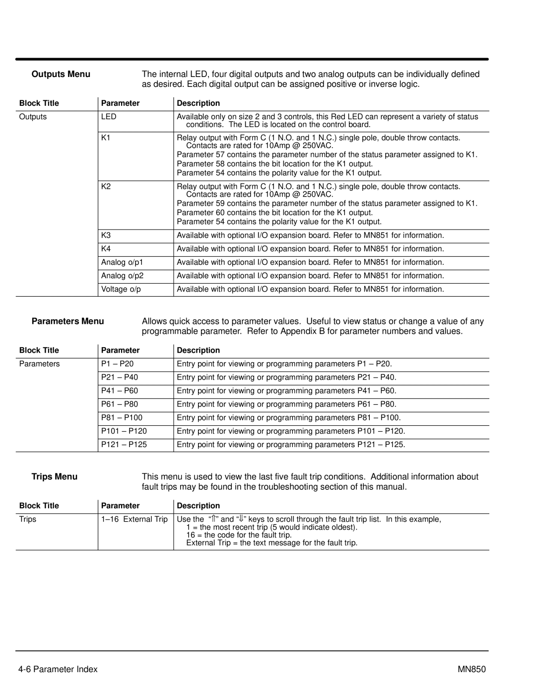
Outputs Menu |
| The internal LED, four digital outputs and two analog outputs can be individually defined | ||
|
| as desired. Each digital output can be assigned positive or inverse logic. | ||
Block Title |
| Parameter |
| Description |
|
| |||
|
|
|
|
|
Outputs |
| LED |
| Available only on size 2 and 3 controls, this Red LED can represent a variety of status |
|
|
|
| conditions. The LED is located on the control board. |
|
|
|
|
|
|
| K1 |
| Relay output with Form C (1 N.O. and 1 N.C.) single pole, double throw contacts. |
|
|
|
| Contacts are rated for 10Amp @ 250VAC. |
|
|
|
| Parameter 57 contains the parameter number of the status parameter assigned to K1. |
|
|
|
| Parameter 58 contains the bit location for the K1 output. |
|
|
|
| Parameter 54 contains the polarity value for the K1 output. |
|
|
|
|
|
|
| K2 |
| Relay output with Form C (1 N.O. and 1 N.C.) single pole, double throw contacts. |
|
|
|
| Contacts are rated for 10Amp @ 250VAC. |
|
|
|
| Parameter 59 contains the parameter number of the status parameter assigned to K1. |
|
|
|
| Parameter 60 contains the bit location for the K1 output. |
|
|
|
| Parameter 54 contains the polarity value for the K1 output. |
|
|
|
|
|
|
| K3 |
| Available with optional I/O expansion board. Refer to MN851 for information. |
|
|
|
|
|
|
| K4 |
| Available with optional I/O expansion board. Refer to MN851 for information. |
|
|
|
|
|
|
| Analog o/p1 |
| Available with optional I/O expansion board. Refer to MN851 for information. |
|
|
|
|
|
|
| Analog o/p2 |
| Available with optional I/O expansion board. Refer to MN851 for information. |
|
|
|
|
|
|
| Voltage o/p |
| Available with optional I/O expansion board. Refer to MN851 for information. |
|
|
|
|
|
Parameters Menu | Allows quick access to parameter values. Useful to view status or change a value of any | |||||
|
|
| programmable parameter. Refer to Appendix B for parameter numbers and values. | |||
Block Title |
| Parameter |
| Description |
| |
|
|
| ||||
|
|
|
|
| ||
Parameters |
| P1 – P20 |
| Entry point for viewing or programming parameters P1 – P20. | ||
|
|
|
|
|
| |
|
| P21 | – P40 |
| Entry point for viewing or programming parameters P21 – P40. | |
|
|
|
|
|
|
|
|
| P41 | – P60 |
| Entry point for viewing or programming parameters P41 | – P60. |
|
|
|
|
|
|
|
|
| P61 | – P80 |
| Entry point for viewing or programming parameters P61 | – P80. |
|
|
|
|
|
|
|
|
| P81 | – P100 |
| Entry point for viewing or programming parameters P81 | – P100. |
|
|
|
|
| ||
|
| P101 – P120 |
| Entry point for viewing or programming parameters P101 – P120. | ||
|
|
|
|
| ||
|
| P121 – P125 |
| Entry point for viewing or programming parameters P121 – P125. | ||
|
|
|
|
|
|
|
Trips Menu |
| This menu is used to view the last five fault trip conditions. Additional information about | ||
|
| fault trips may be found in the troubleshooting section of this manual. | ||
Block Title |
| Parameter |
| Description |
|
| |||
|
|
|
|
|
Trips |
|
| Use the “⇑ ” and “⇓ ” keys to scroll through the fault trip list. In this example, | |
|
|
|
| 1 = the most recent trip (5 would indicate oldest). |
|
|
|
| 16 = the code for the fault trip. |
|
|
|
| External Trip = the text message for the fault trip. |
|
|
|
|
|
| MN850 |
