Section 1
General Information
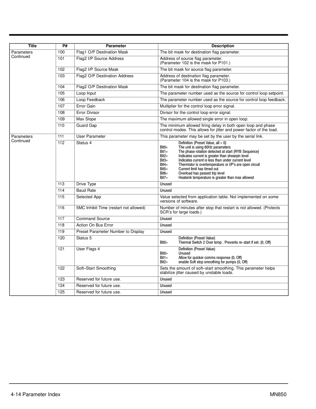
Title | P# | Parameter |
| Description | |
|
|
|
| ||
Parameters | 100 | Flag1 O/P Destination Mask | The bit mask for destination flag parameter. | ||
Continued |
|
|
|
| |
101 | Flag2 I/P Source Address | Address of source flag parameter. | |||
| |||||
|
|
| (Parameter 102 is the mask for P101.) | ||
|
|
|
| ||
| 102 | Flag2 I/P Source Mask | The bit mask for source flag parameter. | ||
|
|
|
| ||
| 103 | Flag2 O/P Destination Address | Address of destination flag parameter. | ||
|
|
| (Parameter 104 is the mask for P103.) | ||
|
|
|
| ||
| 104 | Flag2 O/P Destination Mask | The bit mask for destination flag parameter. | ||
|
|
|
| ||
| 105 | Loop Input | The parameter number used as the source for control loop setpoint. | ||
|
|
|
| ||
| 106 | Loop Feedback | The parameter number used as the source for control loop feedback. | ||
|
|
|
| ||
| 107 | Error Gain | Multiplier for the control loop error signal. | ||
|
|
|
| ||
| 108 | Error Divisor | Divisor for the control loop error signal. | ||
|
|
|
| ||
| 109 | Max Slope | The maximum allowed single error in open loop. | ||
|
|
|
| ||
| 110 | Guard Gap | The minimum allowed firing delay in both open loop and phase | ||
|
|
| control modes. This allows for jitter and power factor of the load. | ||
|
|
|
| ||
Parameters | 111 | User Parameter | This parameter may be set by the user by the serial link. | ||
Continued |
|
|
|
| |
112 | Status 4 |
| Definition (Preset Value, all = 0) | ||
|
| ||||
|
|
| Bit0= | The unit is using 60Hz parameters | |
|
|
| Bit1= | The phase rotation detected at start (RYB Sequence) | |
|
|
| Bit2= | Indicates current is greater than shearpin level | |
|
|
| Bit3= | Indicates current is less than under current level | |
|
|
| Bit4= | Thermistor is overtemperature or I/P's are open circuit | |
|
|
| Bit5= | Current limit has timed out | |
|
|
| Bit6= | Overload has passed trip level | |
|
|
| Bit7= | Heatsink temperature is greater than max allowed | |
|
|
|
|
| |
| 113 | Drive Type | Unused |
| |
|
|
|
|
| |
| 114 | Baud Rate | Unused |
| |
|
|
|
| ||
| 115 | Selected App | Value selected from application table. Not implemented on some | ||
|
|
| versions of software. | ||
|
|
|
| ||
| 116 | 5MC Inhibit Time (restart not allowed) | Number of minutes after stop that restart is not allowed. (Protects | ||
|
|
| SCR’s for large loads.) | ||
|
|
|
|
| |
| 117 | Command Source | Unused |
| |
|
|
|
|
| |
| 118 | Action On Bus Error | Unused |
| |
|
|
|
|
| |
| 119 | Preset Parameter Number to Display | Unused |
| |
|
|
|
|
| |
| 120 | Status 5 |
| Definition (Preset Value) | |
|
|
| Bit0= | Thermal Switch 2 Over temp . Prevents | |
|
|
|
|
| |
| 121 | User Flags 4 |
| Definition (Preset Value) | |
|
|
| Bit0= | Unused | |
|
|
| Bit1= | Allow for quicker comms response (0, Off) | |
|
|
| Bit2= | enable Soft stop smoothing for pumps (0, Off) | |
|
|
|
| ||
| 122 | Sets the amount of | |||
|
|
| stabilize jitter caused by unstable loads. | ||
|
|
|
|
| |
| 123 | Reserved for future use. | Unused |
| |
|
|
|
|
| |
| 124 | Reserved for future use. | Unused |
| |
|
|
|
|
| |
| 125 | Reserved for future use. | Unused |
| |
|
|
|
|
| |
| MN850 |