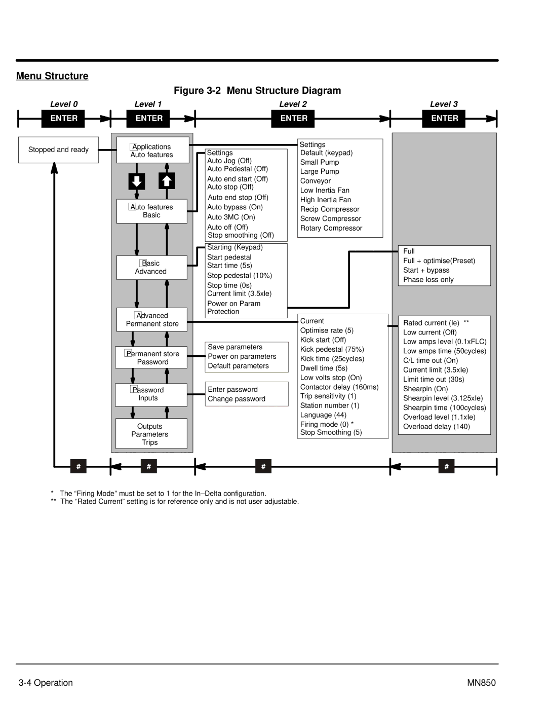
Menu Structure
Level 0
Figure 3-2 Menu Structure Diagram
Level 1 | Level 2 | Level 3 |
ENTER
ENTER |
ENTER
ENTER
Stopped and ready
Applications |
Auto features |
Auto features |
Basic |
Basic |
Advanced |
Advanced |
Permanent store |
Permanent store |
Password |
Password |
Inputs |
Outputs |
Parameters |
Trips |
Settings
Auto Jog (Off) Auto Pedestal (Off)
Auto end start (Off) Auto stop (Off)
Auto end stop (Off) Auto bypass (On) Auto 3MC (On)
Auto off (Off)
Stop smoothing (Off)
Starting (Keypad)
Start pedestal Start time (5s)
Stop pedestal (10%)
Stop time (0s) Current limit (3.5xle)
Power on Param Protection
Save parameters Power on parameters Default parameters
Enter password Change password
Settings
Default (keypad)
Small Pump
Large Pump
Conveyor
Low Inertia Fan
High Inertia Fan
Recip Compressor
Screw Compressor
Rotary Compressor
Current Optimise rate (5) Kick start (Off)
Kick pedestal (75%) Kick time (25cycles) Dwell time (5s)
Low volts stop (On) Contactor delay (160ms) Trip sensitivity (1) Station number (1) Language (44)
Firing mode (0) * Stop Smoothing (5)
Full
Full + optimise(Preset) Start + bypass Phase loss only
Rated current (Ie) ** Low current (Off)
Low amps level (0.1xFLC) Low amps time (50cycles) C/L time out (On)
Current limit (3.5xIe) Limit time out (30s) Shearpin (On)
Shearpin level (3.125xIe) Shearpin time (100cycles) Overload level (1.1xIe)
Overload delay (140)
#
# |
#
#
*The “Firing Mode” must be set to 1 for the
**The “Rated Current” setting is for reference only and is not user adjustable.
MN850 |