Interface Statistics Screen
5.27INTERFACE STATISTICS SCREEN
The Interface Statistics screen is used to gather
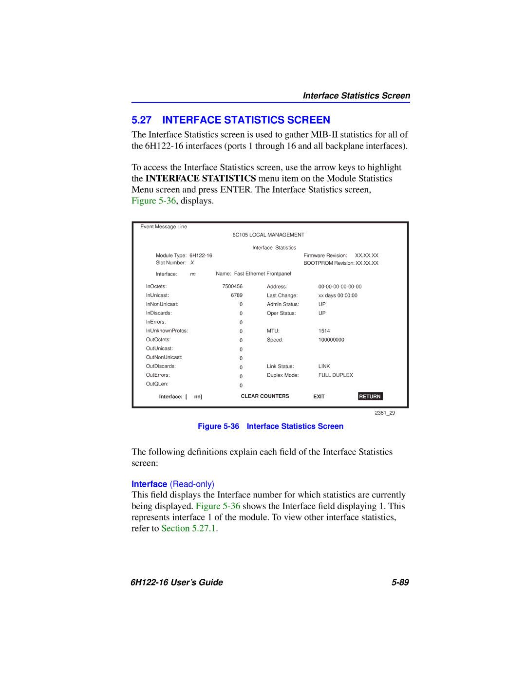
To access the Interface Statistics screen, use the arrow keys to highlight the INTERFACE STATISTICS menu item on the Module Statistics Menu screen and press ENTER. The Interface Statistics screen, Figure
Event Message Line
|
| 6C105 LOCAL MANAGEMENT |
|
| ||
|
|
| Interface Statistics |
|
|
|
Module Type: |
|
| Firmware Revision: | XX.XX.XX | ||
Slot Number: | X |
|
| BOOTPROM Revision: XX.XX.XX | ||
Interface: | nn | Name: Fast Ethernet Frontpanel |
|
|
| |
InOctets: |
| 7500456 | Address: | |||
InUnicast: |
| 6789 | Last Change: | xx days 00:00:00 | ||
InNonUnicast: |
| 0 | Admin Status: | UP |
|
|
InDiscards: |
| 0 | Oper Status: | UP |
|
|
InErrors: |
| 0 |
|
|
|
|
InUnknownProtos: |
| 0 | MTU: | 1514 |
|
|
OutOctets: |
| 0 | Speed: | 100000000 |
|
|
OutUnicast: |
| 0 |
|
|
|
|
OutNonUnicast: |
| 0 |
|
|
|
|
OutDiscards: |
| 0 | Link Status: | LINK |
|
|
OutErrors: |
| 0 | Duplex Mode: | FULL DUPLEX |
|
|
OutQLen: |
| 0 |
|
|
|
|
|
|
|
|
|
| |
|
| CLEAR COUNTERS | EXIT |
|
| |
Interface: [ | nn] |
| RETURN | |||
2361_29
Figure 5-36 Interface Statistics Screen
The following definitions explain each field of the Interface Statistics screen:
Interface
This field displays the Interface number for which statistics are currently being displayed. Figure
|