Chapter 5: Local Management
5.19ETHERNET INTERFACE CONFIGURATION
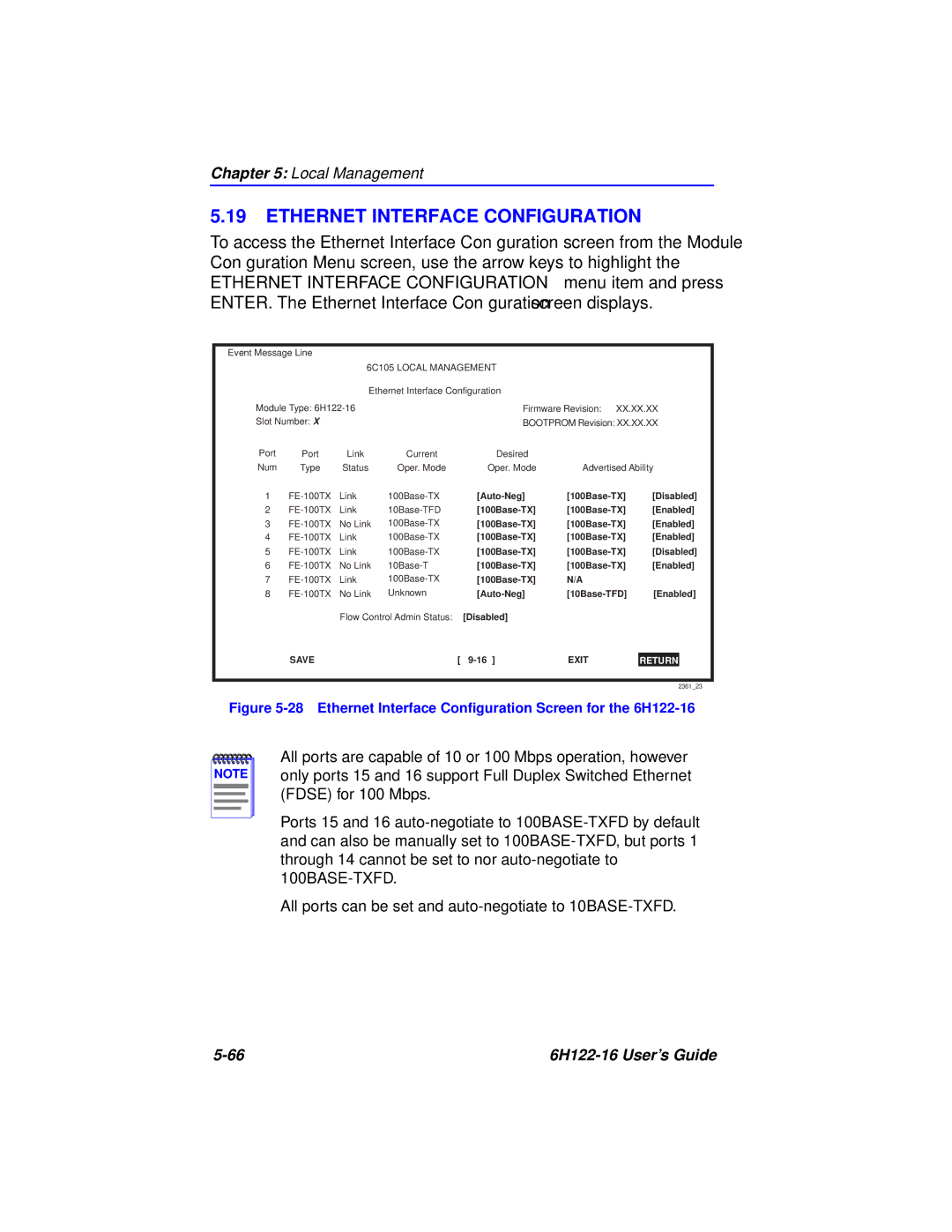
To access the Ethernet Interface Configuration screen from the Module Configuration Menu screen, use the arrow keys to highlight the ETHERNET INTERFACE CONFIGURATION menu item and press ENTER. The Ethernet Interface Configuration screen displays.
Event Message Line
|
| 6C105 LOCAL MANAGEMENT |
|
|
| ||
|
| Ethernet Interface Configuration |
|
|
| ||
Module Type: |
| Firmware Revision: XX.XX.XX | |||||
Slot Number: X |
|
| BOOTPROM Revision: XX.XX.XX | ||||
Port | Port | Link | Current | Desired |
|
|
|
Num | Type | Status | Oper. Mode | Oper. Mode | Advertised Ability | ||
1 | Link | [Disabled] | |||||
2 | Link | [Enabled] | |||||
3 | No Link | [Enabled] | |||||
4 | Link | [Enabled] | |||||
5 | Link | [Disabled] | |||||
6 | No Link | [Enabled] | |||||
7 | Link | N/A |
|
| |||
8 | No Link | Unknown | [Enabled] | ||||
|
| Flow Control Admin Status: [Disabled] |
|
|
| ||
| SAVE |
|
| [ | EXIT |
|
|
|
|
| RETURN |
| |||
2361_23
Figure 5-28 Ethernet Interface Configuration Screen for the 6H122-16
NOTE |
All ports are capable of 10 or 100 Mbps operation, however only ports 15 and 16 support Full Duplex Switched Ethernet (FDSE) for 100 Mbps.
Ports 15 and 16
All ports can be set and
|