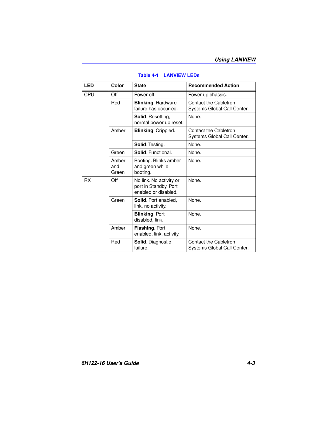
1X 2X 3X 4X 5X 6X 7X 8X 9X 10X 11X 12X 13X 14X 15X 16X
6H122-16 SmartSwitch 6000 Interface Module User’s Guide
6H122-16 RESET
9032361-03
Page
6H122-16 User’s Guide
Only qualified personnel should install the 6H122-16
FCC NOTICE
6H122-16 User’s Guide
INDUSTRY CANADA NOTICE
VCCI NOTICE
CABLETRON SYSTEMS, INC. PROGRAM LICENSE AGREEMENT
6H122-16 User’s Guide
EXCLUSION OF WARRANTY AND DISCLAIMER OF LIABILITY
CABLETRON SOFTWARE PROGRAM LICENSE
UNITED STATES GOVERNMENT RESTRICTED RIGHTS
6H122-16 User’s Guide
SAFETY INFORMATION CLASS 1 LASER TRANSCEIVERS
LASER RADIATION AND CONNECTORS
Manufacturer’s Name Cabletron Systems, Inc
DECLARATION OF CONFORMITY
6H122-16 User’s Guide
Application of Council Directives 89/336/EEC 73/23/EEC
6H122-16 User’s Guide
CHAPTER
CONTENTS
INSTALLATION
TROUBLESHOOTING
viii
Contents
CHAPTER
LOCAL MANAGEMENT
6H122-16 User’s Guide
Contents
APPENDIX A
Contents
SPECIFICATIONS
MODE SWITCH BANK SETTINGS
1.2 STRUCTURE OF THIS GUIDE
1.1 USING THIS GUIDE
CHAPTER INTRODUCTION
Chapter 1 Introduction
1.3 OVERVIEW
1.3.1 Connectivity
1.3.2 Management
6H122-16 User’s Guide
Reset Button COM Port System LED Port Status LEDs Network Ports
RESET
Overview
1.3.6 Remote Monitoring
1.3.4 Switching Options
1.3.5 Full Duplex Switched Ethernet
1.3.3 Distributed Chassis Management
1.3.8 Runtime IP Address Discovery
1.3.7 SmartTrunk
1.3.11 Broadcast Suppression
1.3.9 Port Redirect Function
1.3.10 Auto-Negotiation
1.3.14 Year 2000 Compliant
1.3.13 LANVIEW Diagnostic LEDs
1.3.12 Standards Compatibility
6H122-16 User’s Guide
1.4 DOCUMENT CONVENTIONS
The following conventions are used throughout this document
Chapter 1 Introduction
1.5 GETTING HELP
Cabletron Systems Cabling Guide
1.6 RELATED MANUALS
The following manuals may help to set up, control, and manage the
6H122-16
2.1 SmartTrunk
CHAPTER NETWORK REQUIREMENTS
Chapter 2 Network Requirements
2.2 10BASE-T NETWORK
2.3 100BASE-TX NETWORK
3.1 UNPACKING THE 6H122-16
CHAPTER INSTALLATION
or components
3.2 INSTALLING THE 6H122-16 INTO THE 6C105 CHASSIS
engages the backplane connectors
6H122-16 User’s Guide
Chapter 3 Installation
Figure 3-1 Installing an Interface Module
Connector
3.3 CONNECTING TO THE NETWORK
Figure 3-2 6H122-16 Twisted Pair Connection
RX Receive LED Column
must share a common
SmartSwitch RJ45 Port
Figure 3-3 Cable Pinouts - RJ45 Crossover Cable
Figure 3-4 Cable Pinouts - RJ45 Straight-Through Cable
6H122-16 User’s Guide
3.4 COMPLETING THE INSTALLATION
Chapter 3 Installation
4.1 USING LANVIEW
CHAPTER TROUBLESHOOTING
Figure 4-1 LANVIEW LEDs
Chapter 4 Troubleshooting
RESET
6H122-16 User’s Guide
Color
Using LANVIEW
6H122-16 User’s Guide
Table 4-1 LANVIEW LEDs
Color
Chapter 4 Troubleshooting
6H122-16 User’s Guide
Table 4-1 LANVIEW LEDs Continued
Problem
4.2 TROUBLESHOOTING CHECKLIST
Troubleshooting Checklist
Table 4-3 Troubleshooting Checklist
6H122-16 User’s Guide
Chapter 4 Troubleshooting
Table 4-3 Troubleshooting Checklist Continued
Problem
6H122-16
4.3 USING THE RESET BUTTON
6H122-16 User’s Guide
Chapter 4 Troubleshooting
5.1 OVERVIEW
CHAPTER LOCAL MANAGEMENT
Table 5-1 Keyboard Conventions
5.2 LOCAL MANAGEMENT KEYBOARD CONVENTIONS
Chapter 5 Local Management
6H122-16 User’s Guide
5.3.1 Console Cable Connection
5.3 MANAGEMENT TERMINAL SETUP
6H122-16 User’s Guide
UTP Cable with RJ45 Connectors RJ45-to-DB9 PC Adapter to PC PC
6H122-16 RESET
Chapter 5 Local Management
Display Setup Menu
5.3.2 Management Terminal Setup Parameters
Management Terminal Setup
Table 5-2 VT Terminal Setup
5.3.3 Telnet Connections
5.3.4 Connecting an Uninterruptible Power Supply
RESET
Management Terminal Setup
Figure 5-2 Uninterruptible Power Supply UPS Connection
RESET
Figure 5-3 The Local Management Password Screen
5.4 ACCESSING LOCAL MANAGEMENT
5.4.1 Navigating Local Management Screens
5-10
Figure 5-4 802.1D Switching Mode, LM Screen Hierarchy
Figure 5-5 802.1Q Switching Mode, LM Screen Hierarchy
Chapter 5 Local Management
5.4.3 Exiting Local Management Screens
5.4.2 Selecting Local Management Menu Screen Items
5. Press ENTER. The Password screen displays and the session ends
MODULES
5.5 THE MAIN MENU SCREEN
CHASSIS
CHASSIS CONFIGURATION
5.6 CHASSIS MENU SCREEN
PORT REDIRECT FUNCTION
SNMP COMMUNITY NAMES
SNMP TRAPS
CHASSIS ENVIRONMENTAL
5.7 CHASSIS CONFIGURATION SCREEN
Screen Refresh Time Modifiable
Subnet Mask Modifiable
Chassis Date Modifiable
Chassis Time Modifiable
5.7.1 Setting the IP Address
5.7.3 Setting the Chassis Date
5.7.2 Setting the Subnet Mask
5.7.4 Setting the Chassis Time
5.7.5 Entering a New Screen Refresh Time
5.7.6 Setting the Screen Lockout Time
5.7.7 Setting the Operational Mode
5-23
If the 6H122-16 has been set to 802.1Q SWITCHING, refer to your Port Based VLAN User’s Guide to configure the devices for this type of operation
Chassis Configuration Screen
6H122-16 User’s Guide
Figure 5-11 SNMP Community Names Screen
5.8 SNMP COMMUNITY NAMES SCREEN
5.8.1 Establishing Community Names
5.9 SNMP TRAPS SCREEN
The following explains each field of the SNMP Traps screen
5.9.1 Configuring the Trap Table
Power Supply #X Status Read-Only
5.10 CHASSIS ENVIRONMENTAL SCREEN
Chassis Power Redundancy Read-Only
Chassis Fan Status Read-Only
5.11 PORT REDIRECT FUNCTION SCREEN
Displays which modules are currently set as source modules
5.11.1 Changing Source and Destination Ports
3. Use the arrow keys to highlight the Source Port field
SLOT # Selectable
5.12 MODULE SELECTION SCREEN
5.12.1 Selecting a Module
MODULE CONFIGURATION
5.13 MODULE MENU SCREEN
NETWORK TOOLS
5.14 MODULE CONFIGURATION MENU SCREEN
MODULE STATISTICS
Figure 5-17 Module Configuration Menu Screen
GENERAL CONFIGURATION
The SmartTrunk Configuration screen allows the user to logically group interfaces together to create a greater bandwidth uplink. Refer to the Cabletron Systems SmartTrunk User’s Guide for additional information
5.15 GENERAL CONFIGURATION SCREEN
Page
Page
Section 5.15.10 describes how to set the Management Mode
IP Fragmentation Toggle
5.15.1 Setting the IP Address
Figure 5-19 Configuration Warning Screen
5.15.2 Setting the Subnet Mask
5.15.3 Setting the Default Gateway
5.15.5 Setting the Module Date
5.15.4 Setting the TFTP Gateway IP Address
5.15.6 Setting the Module Time
5.15.7 Entering a New Screen Refresh Time
5.15.8 Setting the Screen Lockout Time
5-50
5.15.9 Setting the Operational Mode
802.1D SWITCHING, 802.1Q SWITCHING, or SECURE FAST VLAN
Chapter 5 Local Management
5-51
Upon saving the new operational mode, the module will reboot
General Configuration Screen
6H122-16 User’s Guide
5.15.10 Setting the Management Mode
6H122-16 User’s Guide
5.15.11 Configuring the COM Port
Section 5.15.1 , Setting the IP Address . Read this entire
General Configuration Screen
3. Use the arrow keys to highlight YES. Press ENTER
5.15.12 Changing the Com Port Application
5.15.13 Clearing NVRAM
5.16 SNMP COMMUNITY NAMES SCREEN
5.15.14 Enabling/Disabling IP Fragmentation
Figure 5-25 SNMP Community Names Screen
access to security-protected fields of read-write
access to the 6H122-16 MIB objects, excluding
5.16.1 Establishing Community Names
Figure 5-26 SNMP Traps Screen
5.17 SNMP TRAPS SCREEN
5.17.1 Configuring the Trap Table
Figure 5-27 Switch Configuration Screen
5.18 SWITCH CONFIGURATION SCREEN
The following describe each field of the Switch Configuration screen
5.18.1 Setting the STA
5.18.3 Setting Enabling or Disabling the Port Status
5.18.2 Setting the Age Time
6H122-16 User’s Guide
5.19 ETHERNET INTERFACE CONFIGURATION
Chapter 5 Local Management
5-66
Displays the number of the front panel interface
5.19.1 Configuring the Ports
5.19.2 Setting the Operational Mode
5.19.4 Setting the Flow Control Admin Status
5.19.3 Setting the Advertised Ability
5.20 MODULE SPECIFIC CONFIGURATION MENU SCREEN
Figure 5-29 Module Specific Configuration Screen
SYSTEM RESOURCES
5.21 SYSTEM RESOURCES SCREEN
The following briefly explains each field of the System Resources screen
5.22 FLASH DOWNLOAD SCREEN
5.21.1 Setting the Reset Peak Utilization
Download Method Selectable
The following briefly explains each field of the Flash Download screen
5.22.1 Image File Download Using TFTP
5.22.2 Image File Download Using RUNTIME
5.22.3 Image File Download Using BootP
5.23 PORT REDIRECT FUNCTION SCREEN
Figure 5-32 Port Redirect Function Screen
5.23.1 Changing Source and Destination Ports
5.24 BROADCAST SUPPRESSION SCREEN
Peak Rate Read-Only
Broadcast Suppression Screen
PORT # Read-only
Total RX Read-Only
Time Since Peak Read-Only
5.24.1 Setting the Threshold
5.24.2 Setting the Reset Peak Switch
Reset Peak Toggle
5-85
5.25 MODULE STATISTICS MENU SCREEN
Module Statistics Menu Screen
6H122-16 User’s Guide
The Module Statistics Menu screen displays the following menu items
Figure 5-35 Switch Statistics Screen
5.26 SWITCH STATISTICS SCREEN
5.26.1 Using the Clear Counters Command
Interface Read-only
5.27 INTERFACE STATISTICS SCREEN
InUnicast Read-only
InErrors Read-only
Name Read-only
InOctets Read-only
OutDiscards Read-only
OutErrors Read-only
Admin Status Read-only
OutNonUnicast Read-only
5.27.1 Displaying Interface Statistics
5.27.2 Using the Clear Counters Command
RMON Index Read-only
5.28 RMON STATISTICS SCREEN
This field displays the name of the entity that configured this entry
The total number of undersized frames with a bad CRC
256 - 511 Octets Read-only
Index nn Command
CLEAR COUNTERS Command
128 - 255 Octets Read-only
5.28.1 Displaying RMON Statistics
5.28.2 Using the Clear Counters Command
Use lower case when entering commands in Network Tools
5.29 NETWORK TOOLS
Type help at the prompt to list all the commands that are
Options
command
Syntax
Description
Options
5.29.1 Built-in Commands
arp options
Syntax
Options
Example
Syntax
Description
Example
Syntax
Description
Options
Options
Example
Syntax
Description
Example
Syntaxreset
Not Applicable
Options
Description
not reached, the command displays all next-hop
Example
Syntax
Description
Options
Example
Syntax
Description
5.29.2 Special Commands
linktrap
Syntax
6H122-16 User’s Guide
Chapter 5 Local Management
5-108
A.3 ENVIRONMENTAL REQUIREMENTS
APPENDIX A SPECIFICATIONS
A.1 DEVICE SPECIFICATIONS
A.2 PHYSICAL PROPERTIES
REGULATORY COMPLIANCE
A.4 INPUT/OUTPUT PORTS
A.5 COM PORT PINOUT ASSIGNMENTS
B.1 REQUIRED TOOLS
APPENDIX B MODE SWITCH BANK SETTINGS
B.2 SETTING THE MODE SWITCH
Switch definitions and positions are as follows
Switch 7 - Clear NVRAM. Changing the position of this switch resets NVRAM on the next power up. ALL user entered parameters, such as IP addresses, subnet masks, SNMP traps, and switching functions are restored to their factory default settings
6H122-16 User’s Guide
Appendix B Mode Switch Bank Settings
Index-1
INDEX
Numerics
6H122-16 User’s Guide
Page
Index-3
Index
6H122-16 User’s Guide
Index
Index-4