Verifying Connectivity
Verifying Connectivity
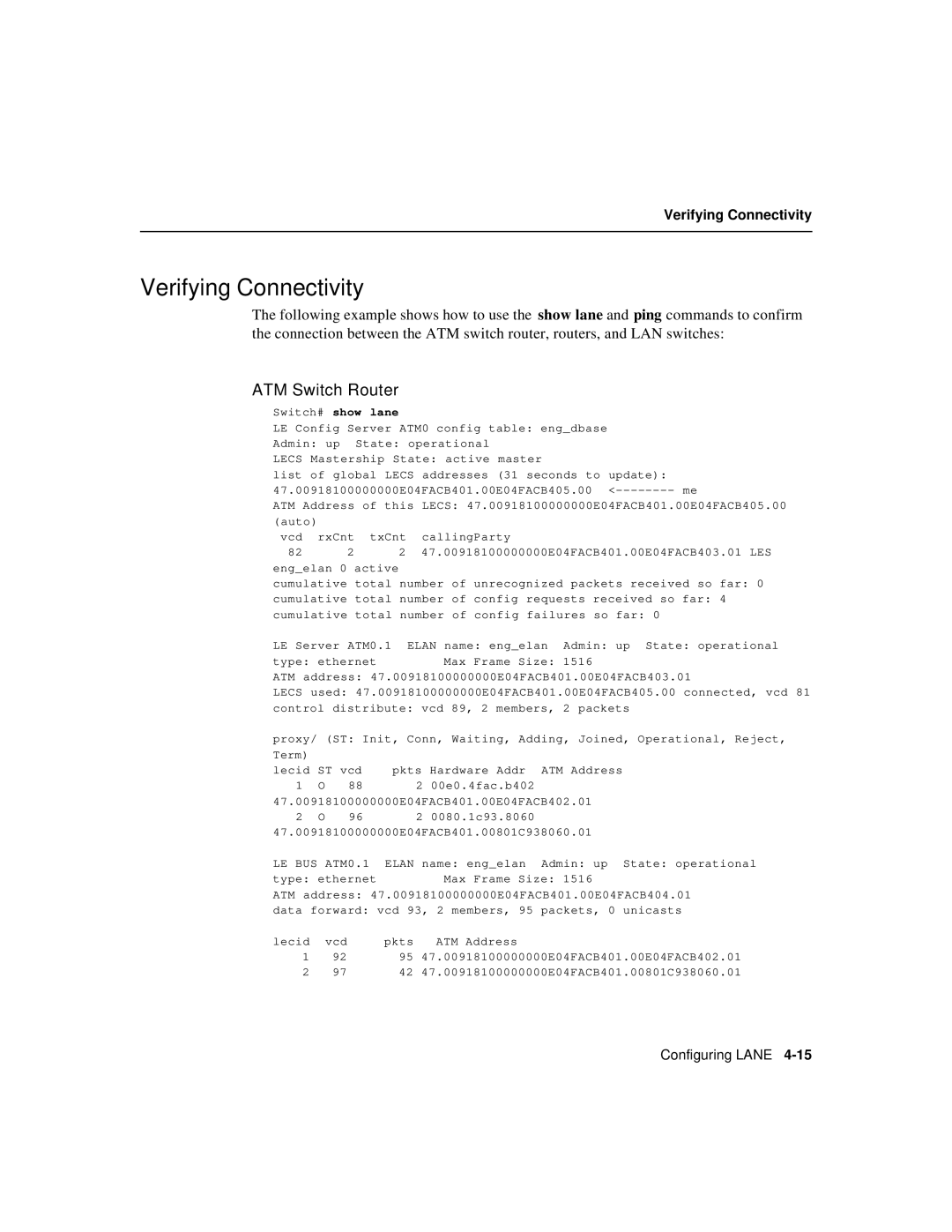
The following example shows how to use the show lane and ping commands to confirm the connection between the ATM switch router, routers, and LAN switches:
ATM Switch Router
Switch# show lane
LE Config Server ATM0 config table: eng_dbase
Admin: up State: operational
LECS Mastership State: active master
list of global LECS addresses (31 seconds to update): 47.00918100000000E04FACB401.00E04FACB405.00
ATM Address of this LECS: 47.00918100000000E04FACB401.00E04FACB405.00
(auto) |
|
| |
vcd | rxCnt | txCnt | callingParty |
82 | 2 | 2 | 47.00918100000000E04FACB401.00E04FACB403.01 LES |
eng_elan 0 active
cumulative total number of unrecognized packets received so far: 0
cumulative total number of config requests received so far: 4
cumulative total number of config failures so far: 0
LE Server ATM0.1 ELAN name: eng_elan Admin: up State: operational
type: ethernet Max Frame Size: 1516
ATM address: 47.00918100000000E04FACB401.00E04FACB403.01
LECS used: 47.00918100000000E04FACB401.00E04FACB405.00 connected, vcd 81
control distribute: vcd 89, 2 members, 2 packets
proxy/ (ST: Init, Conn, Waiting, Adding, Joined, Operational, Reject,
Term) |
|
|
|
|
lecid ST vcd | pkts Hardware Addr | ATM Address | ||
1 | O | 88 | 2 00e0.4fac.b402 |
|
47.00918100000000E04FACB401.00E04FACB402.01 | ||||
2 | O | 96 | 2 0080.1c93.8060 |
|
47.00918100000000E04FACB401.00801C938060.01 | ||||
LE BUS ATM0.1 | ELAN name: eng_elan | Admin: up State: operational | ||
type: ethernet | Max Frame Size: 1516 | |||
ATM address: 47.00918100000000E04FACB401.00E04FACB404.01
data forward: vcd 93, 2 members, 95 packets, 0 unicasts
lecid | vcd | pkts | ATM Address |
1 | 92 | 95 | 47.00918100000000E04FACB401.00E04FACB402.01 |
2 | 97 | 42 | 47.00918100000000E04FACB401.00801C938060.01 |
Configuring LANE
