Verifying Connectivity
Success rate is 100 percent (5/5),
ATM_Switch# ping 172.16.0.3
Type escape sequence to abort.
Sending 5,
!!!!!
Success rate is 100 percent (5/5),
Displaying the LANE Client Configuration on the ATM Switch Router
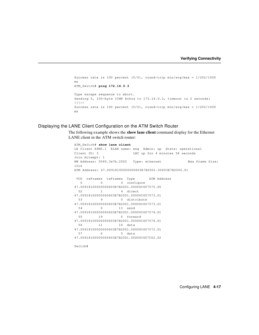
The following example shows the show lane client command display for the Ethernet LANE client in the ATM switch router:
ATM_Switch# show lane client |
|
| |
LE | Client ATM0.1 ELAN name: eng Admin: up | State: operational | |
Client ID: 3 | LEC up for 4 minutes 58 seconds | ||
Join Attempt: 1 |
|
| |
HW | Address: 0060.3e7b.2002 | Type: ethernet | Max Frame Size: |
1516
ATM Address: 47.00918100000000603E7B2001.00603E7B2002.01
VCD | rxFrames | txFrames | Type | ATM Address |
0 | 0 | 0 | configure |
|
47.00918100000000603E7B2001.00000C407575.00 | ||||
52 | 1 | 4 | direct |
|
47.00918100000000603E7B2001.00000C407573.01 | ||||
53 | 9 | 0 | distribute |
|
47.00918100000000603E7B2001.00000C407573.01 | ||||
54 | 0 | 13 | send |
|
47.00918100000000603E7B2001.00000C407574.01 | ||||
55 | 19 | 0 | forward |
|
47.00918100000000603E7B2001.00000C407574.01 | ||||
56 | 11 | 10 | data |
|
47.00918100000000603E7B2001.00000C407572.01 | ||||
57 | 6 | 5 | data |
|
47.00918100000000603E7B2001.00000C407C02.02
Switch#
Configuring LANE
