Configuring the ATM Switch Router
Note If the PVC terminates onan ATM switch router, you must terminate the connection on the route processor interface ATM 0. The atm pvc 0
Switch(config-if)# atm pvc 2 100 interface atm 0 0 any-vci
Example
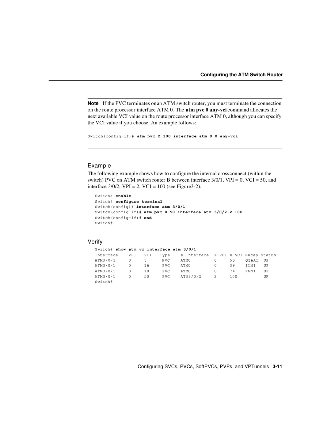
The following example shows how to configure the internal crossconnect (within the switch) PVC on ATM switch router B between interface 3/0/1, VPI = 0, VCI = 50, and interface 3/0/2, VPI = 2, VCI = 100 (see
Switch> enable
Switch# configure terminal
Switch(config)# interface atm 3/0/1
Switch#
Verify
Switch# show atm vc interface atm 3/0/1 |
|
|
|
| ||||
Interface | VPI | VCI | Type | |||||
ATM3/0/1 | 0 | 5 | PVC | ATM0 | 0 | 55 | QSAAL | UP |
ATM3/0/1 | 0 | 16 | PVC | ATM0 | 0 | 39 | ILMI | UP |
ATM3/0/1 | 0 | 18 | PVC | ATM0 | 0 | 74 | PNNI | UP |
ATM3/0/1 | 0 | 50 | PVC | ATM3/0/2 | 2 | 100 |
| UP |
Switch# |
|
|
|
|
|
|
|
|
Configuring SVCs, PVCs, SoftPVCs, PVPs, and VPTunnels
