Chapter 2 Feature Card and Carrier Card Guidelines
Getting Help
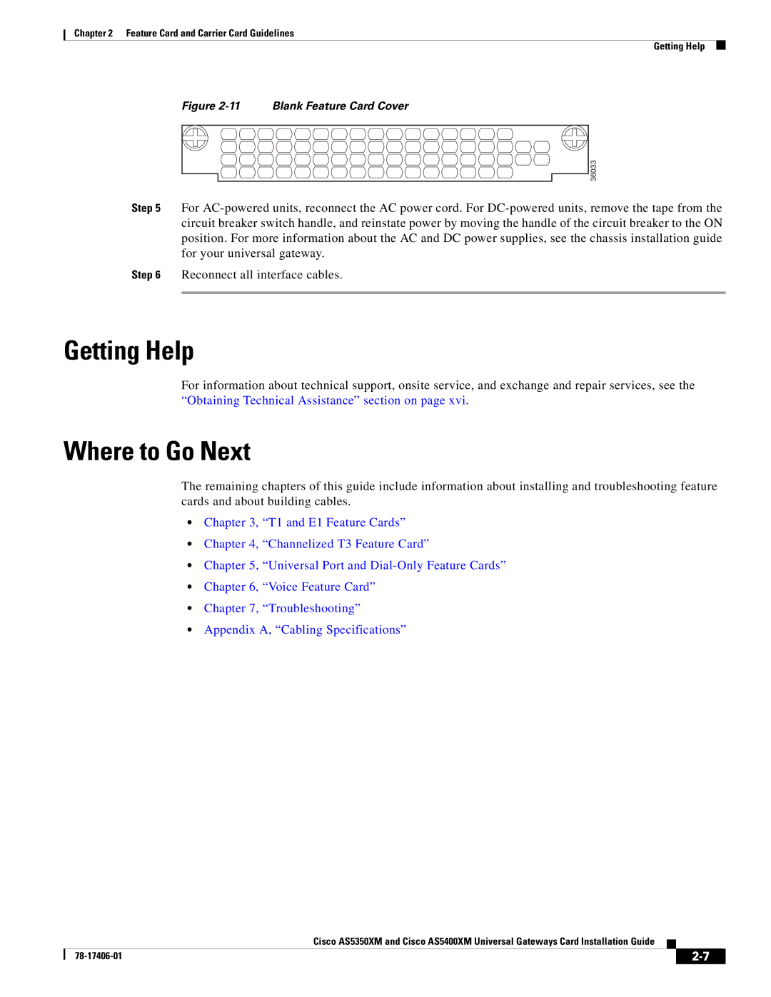
Figure 2-11 Blank Feature Card Cover
36033
Step 5 For
Step 6 Reconnect all interface cables.
Getting Help
For information about technical support, onsite service, and exchange and repair services, see the “Obtaining Technical Assistance” section on page xvi.
Where to Go Next
The remaining chapters of this guide include information about installing and troubleshooting feature cards and about building cables.
•Chapter 3, “T1 and E1 Feature Cards”
•Chapter 4, “Channelized T3 Feature Card”
•Chapter 5, “Universal Port and
•Chapter 6, “Voice Feature Card”
•Chapter 7, “Troubleshooting”
•Appendix A, “Cabling Specifications”
Cisco AS5350XM and Cisco AS5400XM Universal Gateways Card Installation Guide
|
|
| |
|
|