Appendix A Cabling Specifications
Table |
|
|
|
| ||||||||||||||
|
|
|
|
|
|
|
|
|
|
|
|
|
|
|
|
|
|
|
|
| Signal | Description | Direction |
|
|
| |||||||||||
|
|
|
|
|
|
|
|
|
|
|
|
|
|
|
|
|
|
|
| RX Ring | Twisted Pair #1 |
| <— |
|
|
| |||||||||||
|
|
|
|
|
|
|
|
|
|
|
|
|
|
|
|
|
|
|
| RX Shield | Twisted Pair #3 |
|
|
|
|
|
|
|
| ||||||||
|
|
|
|
|
|
|
|
|
|
|
|
|
|
|
|
|
|
|
| TX Tip | Twisted Pair #2 |
|
|
|
| ||||||||||||
|
|
|
|
|
|
|
|
|
|
|
|
|
|
|
|
|
|
|
| TX Ring | Twisted Pair #2 |
|
|
|
| ||||||||||||
|
|
|
|
|
|
|
|
|
|
|
|
|
|
|
|
|
|
|
| TX Shield | Twisted Pair #4 |
|
|
|
|
|
|
|
| ||||||||
|
|
|
|
|
|
|
|
|
|
|
|
|
|
|
|
|
| |
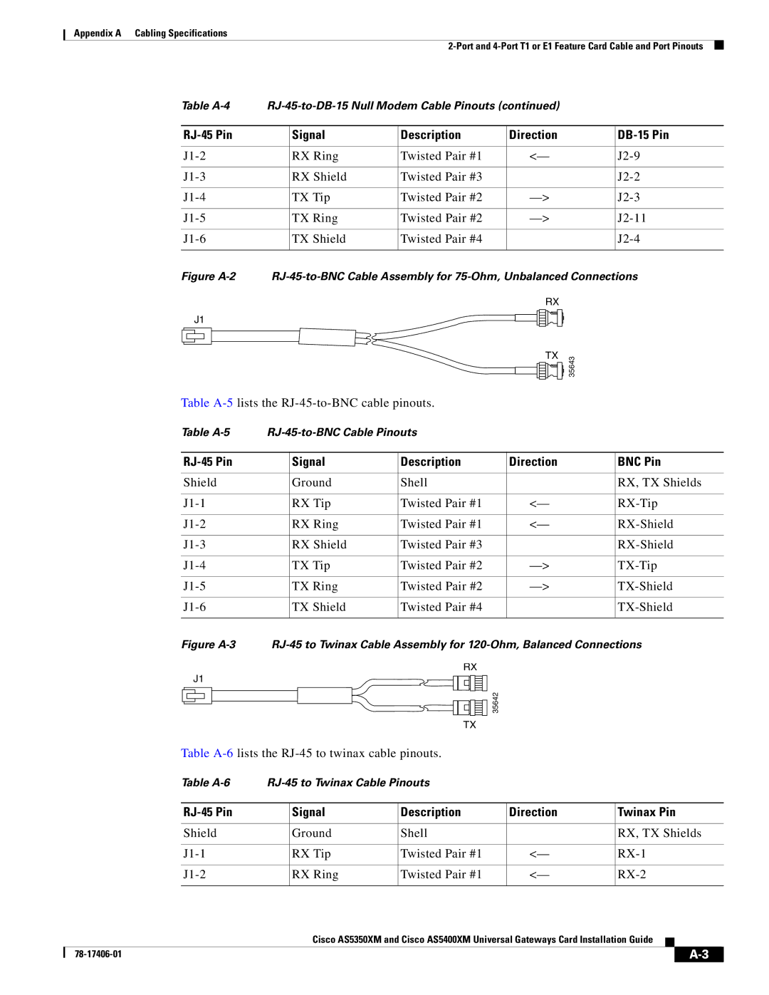
Figure |
| |||||||||||||||||
|
|
|
|
|
|
|
|
|
|
|
| RX |
|
|
|
| ||
|
| J1 |
|
|
|
|
|
|
|
|
|
|
|
|
| |||
|
|
|
|
|
|
|
|
|
|
|
|
|
|
| ||||
|
|
|
|
|
|
|
|
|
|
|
|
|
|
| ||||
|
|
|
|
|
|
|
|
|
|
|
|
|
|
|
|
|
|
|
|
|
|
|
|
|
|
|
|
|
|
| TX |
|
| 35643 |
| ||
|
|
|
|
|
|
|
|
|
|
|
|
|
|
| ||||
|
|
|
|
|
|
|
|
|
|
|
|
|
|
| ||||
|
|
|
|
|
|
|
|
|
|
|
|
|
|
|
|
|
| |
|
|
|
|
|
|
|
|
|
|
|
|
|
|
|
|
| ||
|
|
|
|
|
|
|
|
|
|
|
|
|
|
|
| |||
|
|
|
|
|
|
|
|
|
|
|
|
|
|
|
|
|
|
|
Table
Table |
|
|
|
|
| |||||||||||||||
|
|
|
|
|
|
|
|
|
|
|
|
|
|
|
|
|
|
|
|
|
|
| Signal | Description |
|
|
| Direction | BNC Pin | ||||||||||||
|
|
|
|
|
|
|
|
|
|
|
|
|
|
|
|
|
|
|
|
|
Shield |
| Ground | Shell |
|
|
|
| RX, TX Shields | ||||||||||||
|
|
|
|
|
|
|
|
|
|
|
|
|
|
|
|
|
|
|
|
|
| RX Tip | Twisted Pair #1 |
|
|
| <— | ||||||||||||||
|
|
|
|
|
|
|
|
|
|
|
|
|
|
|
|
|
|
|
|
|
| RX Ring | Twisted Pair #1 |
|
|
| <— | ||||||||||||||
|
|
|
|
|
|
|
|
|
|
|
|
|
|
|
|
|
|
|
|
|
| RX Shield | Twisted Pair #3 |
|
|
|
| ||||||||||||||
|
|
|
|
|
|
|
|
|
|
|
|
|
|
|
|
|
|
|
|
|
| TX Tip | Twisted Pair #2 |
|
|
| |||||||||||||||
|
|
|
|
|
|
|
|
|
|
|
|
|
|
|
|
|
|
|
|
|
| TX Ring | Twisted Pair #2 |
|
|
| |||||||||||||||
|
|
|
|
|
|
|
|
|
|
|
|
|
|
|
|
|
|
|
|
|
| TX Shield | Twisted Pair #4 |
|
|
|
| ||||||||||||||
|
|
|
|
|
|
|
|
|
|
|
|
|
|
|
|
|
|
|
| |
Figure |
| |||||||||||||||||||
|
|
|
|
|
|
|
|
|
| RX |
|
|
|
|
| |||||
| J1 |
|
|
|
|
|
|
|
|
|
|
|
|
| 35642 |
|
| |||
|
|
|
|
|
|
|
|
|
|
|
|
|
|
|
|
|
|
|
| |
|
|
|
|
|
|
|
|
|
| TX |
|
|
|
|
| |||||
Table
Table
|
|
| Signal | Description | Direction | Twinax Pin | |||
|
|
|
|
|
|
| |||
|
| Shield | Ground | Shell |
| RX, TX Shields | |||
|
|
|
|
|
|
| |||
|
| RX Tip | Twisted Pair #1 | <— | |||||
|
|
|
|
|
|
| |||
|
| RX Ring | Twisted Pair #1 | <— | |||||
|
|
|
|
|
|
|
|
|
|
|
|
| Cisco AS5350XM and Cisco AS5400XM Universal Gateways Card Installation Guide |
|
|
| |||
|
|
|
| ||||||
|
|
|
|
|
|
|
|
|
|
|
|
|
|
|
|
|
|
| |
|
|
|
|
|
|
| |||