Chapter 6 Voice Feature Card
Replacing PVDM2 Modules in the Voice Feature Card
Figure |
|
|
| |
5 |
| 4 | 3 |
|
2 | 1 |
| 0 | 135740 |
|
| |||
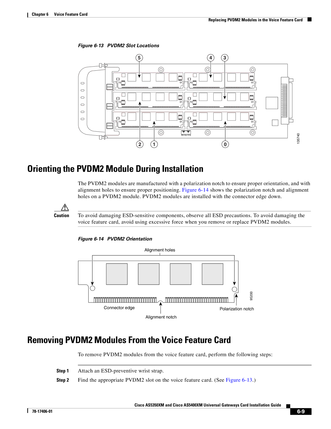
Orienting the PVDM2 Module During Installation
The PVDM2 modules are manufactured with a polarization notch to ensure proper orientation, and with alignment holes to ensure proper positioning. Figure
Caution To avoid damaging
Figure 6-14 PVDM2 Orientation
Alignment holes
| 95200 |
Connector edge | Polarization notch |
| Alignment notch |
Removing PVDM2 Modules From the Voice Feature Card
To remove PVDM2 modules from the voice feature card, perform the following steps:
Step 1 Attach an
Step 2 Find the appropriate PVDM2 slot on the voice feature card. (See Figure
Cisco AS5350XM and Cisco AS5400XM Universal Gateways Card Installation Guide
|
|
| |
|
|