Chapter 3 T1 and E1 Feature Cards
Online Installation and Removal of the T1 or E1 Feature Card
Installing the T1 or E1 Feature Card
Warning Do not work on the system or connect or disconnect cables during periods of lightning activity. Statement 1001
Warning The E1 interface card may only be installed in an
Warning The telecommunications lines must be disconnected 1) before unplugging the main power connector and/or 2) while the housing is open. Statement 89
Note When you replace a feature card in a slot with a new feature card of the same type, the system software recognizes the new feature card and brings up the trunk interfaces automatically. If you replace the existing feature card with a new feature card of a different type, you must reconfigure the system. For configuration details, see the Cisco AS5350XM and Cisco AS5400XM Universal Gateways Software Configuration Guide.
To install the T1 or E1 feature card, follow these steps:
Step 1 Attach an
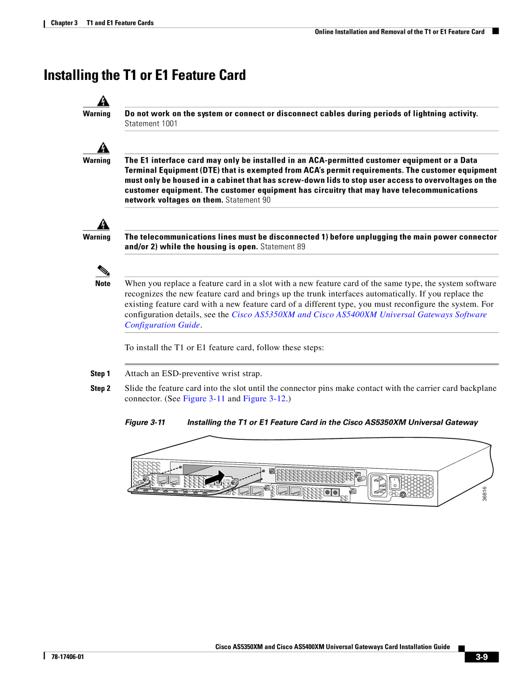
Step 2 Slide the feature card into the slot until the connector pins make contact with the carrier card backplane connector. (See Figure
Figure 3-11 Installing the T1 or E1 Feature Card in the Cisco AS5350XM Universal Gateway
0 | 1 | Rx Tx |
|
|
2 PRI |
ACT OK
36816
Cisco AS5350XM and Cisco AS5400XM Universal Gateways Card Installation Guide
|
|
| |
|
|