Appendix A Cabling Specifications
CT3 Feature Card Cable and Port Pinouts
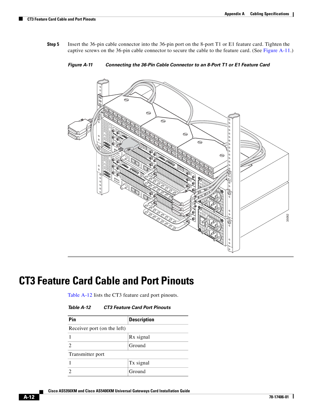
Step 5 Insert the
Figure A-11 Connecting the 36-Pin Cable Connector to an 8-Port T1 or E1 Feature Card
35062
CT3 Feature Card Cable and Port Pinouts
Table
Table
Pin
Description
Receiver port (on the left)
| 1 | Rx signal |
| ||||
|
|
|
| ||||
2 | Ground | ||||||
|
|
|
|
|
|
|
|
|
|
|
| Transmitter port |
|
|
|
|
|
|
| ||||
1 | Tx signal | ||||||
|
|
|
| ||||
2 | Ground | ||||||
|
|
|
|
|
|
| |
|
|
| Cisco AS5350XM and Cisco AS5400XM Universal Gateways Card Installation Guide | ||||
|
|
| |||||
|
|
|
|
|
|
|
|
|
|
|
|
| |||
|
|
|
|
| |||