Appendix A Cabling Specifications
Table
Table |
|
| ||
| Signal | Description | Direction | |
Shield | Ground | Shell/Braid |
| Shield |
RX Tip | Twisted Pair #1 | <— | ||
RX Ring | Twisted Pair #1 | <— | ||
RX Shield |
|
|
| |
TX Tip | Twisted Pair #2 | |||
TX Ring | Twisted Pair #2 | |||
TX Shield |
|
|
| |
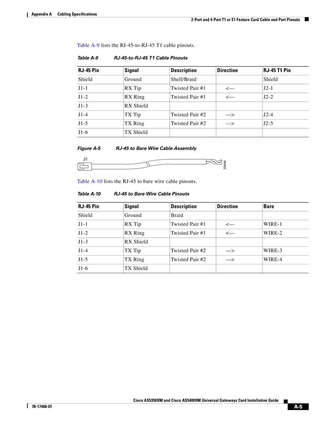
Figure |
|
|
| |
J1 |
|
| 35646 |
|
|
|
|
| |
Table
Table |
|
| |||
|
|
|
|
|
|
|
| Signal | Description | Direction | Bare |
|
|
|
|
|
|
Shield |
| Ground | Braid |
|
|
|
|
|
|
|
|
| RX Tip | Twisted Pair #1 | <— | ||
|
|
|
|
|
|
| RX Ring | Twisted Pair #1 | <— | ||
|
|
|
|
|
|
| RX Shield |
|
|
| |
|
|
|
|
|
|
| TX Tip | Twisted Pair #2 | |||
|
|
|
|
|
|
| TX Ring | Twisted Pair #2 |
| ||
|
|
|
|
|
|
|
| TX Shield |
|
|
|
|
|
|
|
|
|
Cisco AS5350XM and Cisco AS5400XM Universal Gateways Card Installation Guide
|
| |
|