Chapter 3 T1 and E1 Feature Cards
Online Installation and Removal of the T1 or E1 Feature Card
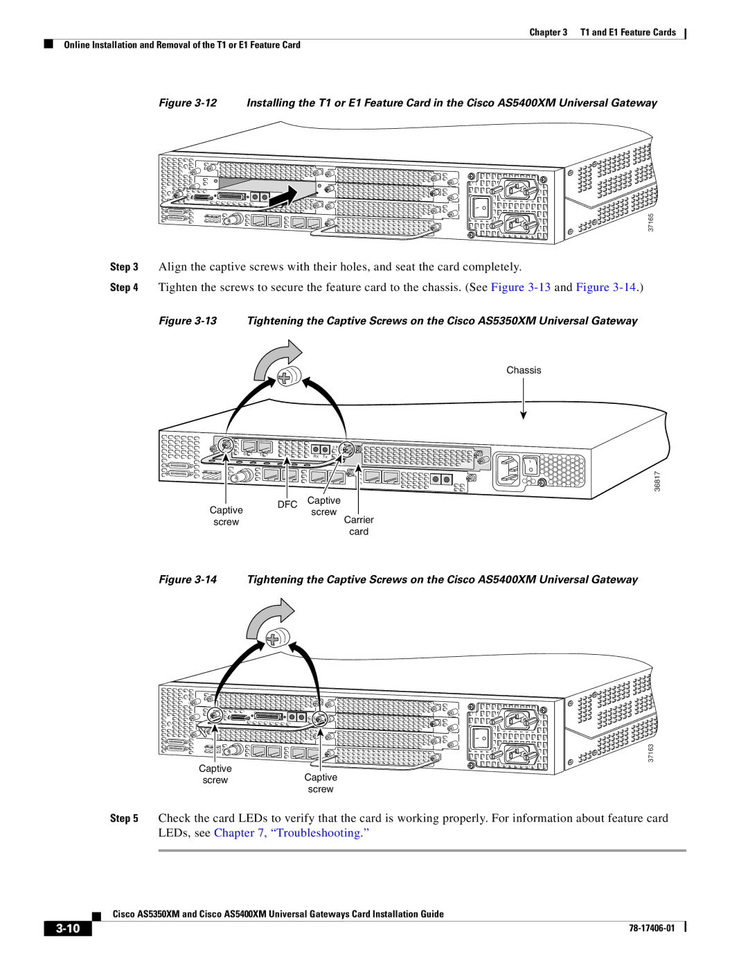
Figure 3-12 Installing the T1 or E1 Feature Card in the Cisco AS5400XM Universal Gateway
37165
Step 3 Align the captive screws with their holes, and seat the card completely.
Step 4 Tighten the screws to secure the feature card to the chassis. (See Figure
Figure 3-13 Tightening the Captive Screws on the Cisco AS5350XM Universal Gateway
Chassis
0 | 1 |
Rx Tx
2 PRI![]()
![]()
![]()
ACT ![]()
36817
Captive | DFC | Captive | |
screw | |||
| |||
screw |
| Carrier | |
|
| card |
Figure 3-14 Tightening the Captive Screws on the Cisco AS5400XM Universal Gateway
Captive
screwCaptive screw
37163
Step 5 Check the card LEDs to verify that the card is working properly. For information about feature card LEDs, see Chapter 7, “Troubleshooting.”
Cisco AS5350XM and Cisco AS5400XM Universal Gateways Card Installation Guide
| ||
|