Chapter 1 Cisco SFS 3012R Server Switch Overview
Cisco SFS 3012R Server Switch Chassis
Cisco SFS 3012R Server Switch Chassis
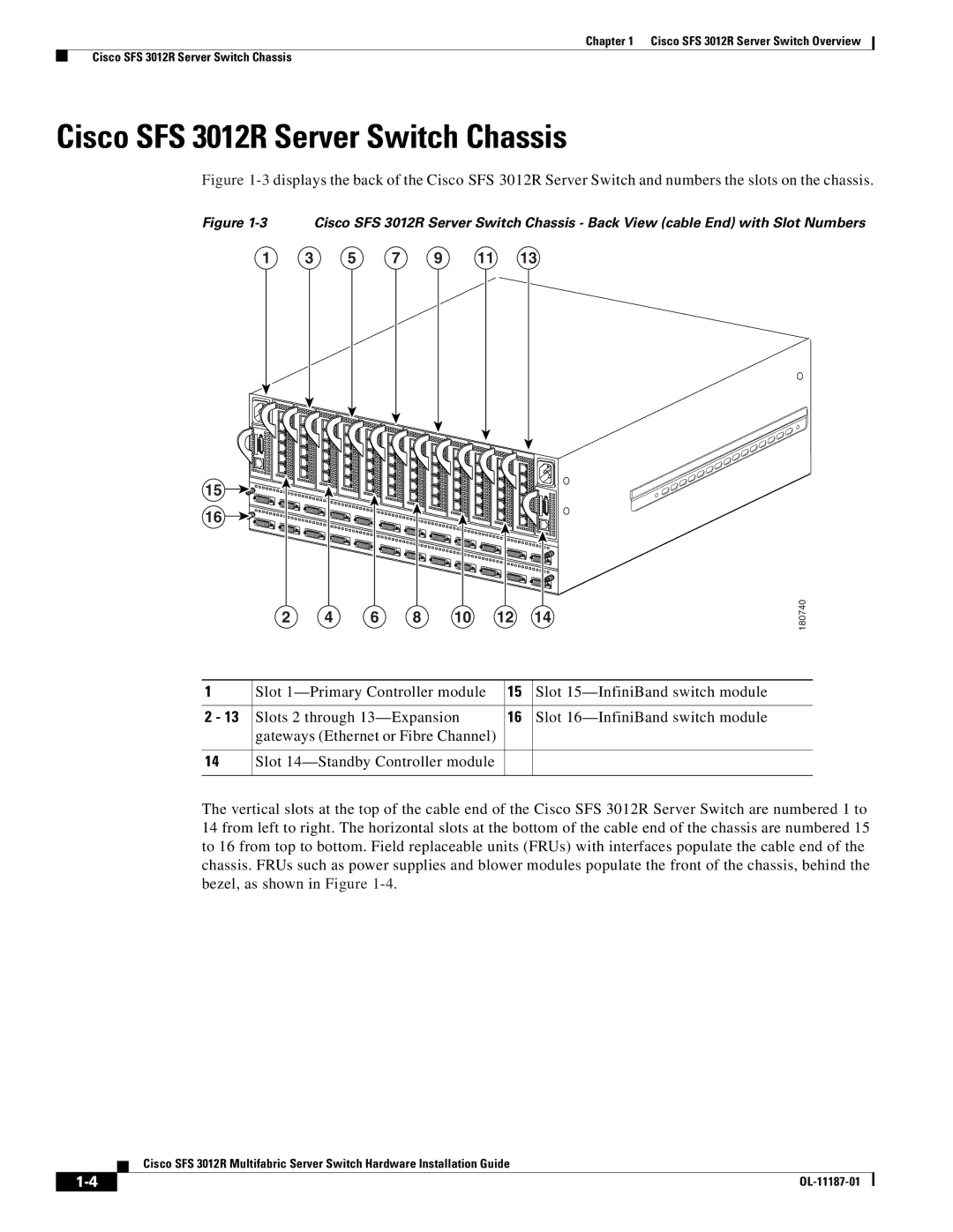
Figure 1-3 displays the back of the Cisco SFS 3012R Server Switch and numbers the slots on the chassis.
Figure 1-3 Cisco SFS 3012R Server Switch Chassis - Back View (cable End) with Slot Numbers
1 | 3 | 5 | 7 | 9 | 11 | 13 |
15 |
16 |
2 4 6 8 10 12 14
180740
1 | Slot | 15 | Slot |
|
|
|
|
2 - 13 | Slots 2 through | 16 | Slot |
| gateways (Ethernet or Fibre Channel) |
|
|
|
|
|
|
14 | Slot |
|
|
|
|
|
|
The vertical slots at the top of the cable end of the Cisco SFS 3012R Server Switch are numbered 1 to 14 from left to right. The horizontal slots at the bottom of the cable end of the chassis are numbered 15 to 16 from top to bottom. Field replaceable units (FRUs) with interfaces populate the cable end of the chassis. FRUs such as power supplies and blower modules populate the front of the chassis, behind the bezel, as shown in Figure
Cisco SFS 3012R Multifabric Server Switch Hardware Installation Guide
|
| |
|