Chapter 1 Cisco SFS 3012R Server Switch Overview
Cisco SFS 3012R Server Switch Components
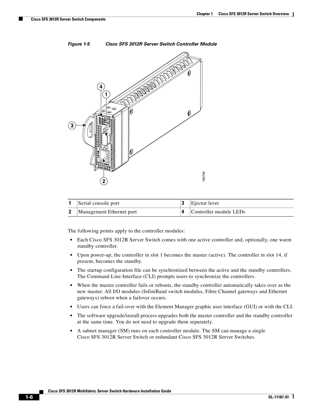
Figure 1-5 Cisco SFS 3012R Server Switch Controller Module
4
1
3
2
180749
1 | Serial console port | 3 | Ejector lever |
|
|
|
|
2 | Management Ethernet port | 4 | Controller module LEDs |
|
|
|
|
The following points apply to the controller modules:
•Each Cisco SFS 3012R Server Switch comes with one active controller and, optionally, one warm standby controller.
•Upon
•The startup configuration file can be synchronized between the active and the standby controllers. The Command Line Interface (CLI) prompts users to synchronize the controllers.
•When the master controller fails or reboots, the standby controller automatically takes over as the new master. All I/O modules (InfiniBand switch modules, Fibre Channel gateways and Ethernet gateways) reboot when a failover occurs.
•Users can force a
•The software upgrade/install process upgrades both the master controller and the standby controller at the same time. You do not need to upgrade them separately.
•A subnet manager (SM) runs on each controller module. The SM can manage a single Cisco SFS 3012R Server Switch or redundant Cisco SFS 3012R Server Switches.
Cisco SFS 3012R Multifabric Server Switch Hardware Installation Guide
|
| |
|