Chapter 3 Installing and Removing Server Switch Field Replaceable Units (FRUs)
Installing a Blower Module
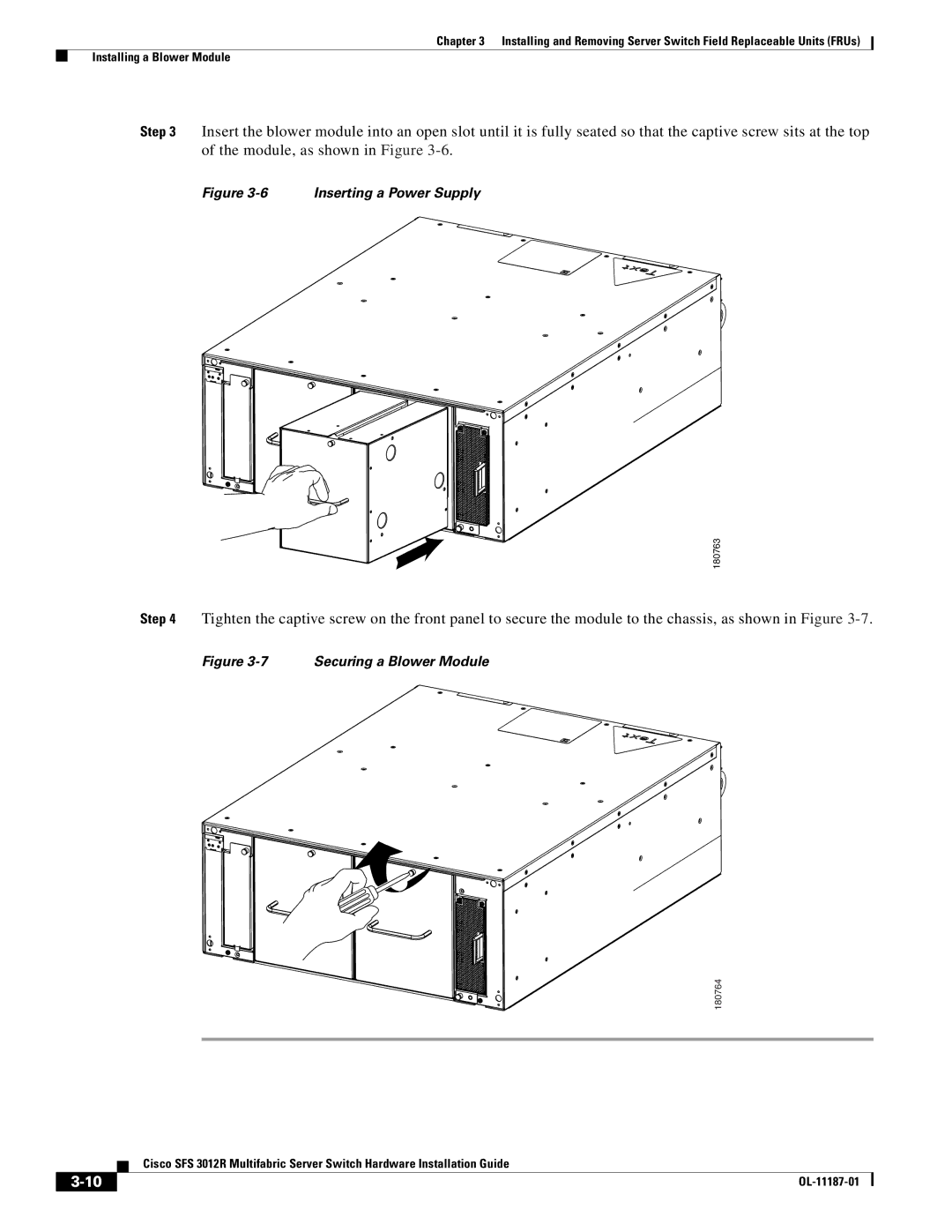
Step 3 Insert the blower module into an open slot until it is fully seated so that the captive screw sits at the top of the module, as shown in Figure
Figure 3-6 Inserting a Power Supply
180763
Step 4 Tighten the captive screw on the front panel to secure the module to the chassis, as shown in Figure
Figure 3-7 Securing a Blower Module
180764
| Cisco SFS 3012R Multifabric Server Switch Hardware Installation Guide |
|
